RH850/F1Kx, RH850/F1K Series Hardware Design Guide
R01AN3841ED0110 Rev. 1.10 Page 67 of 108
August 8, 2019
3. Oscillator
3.1 Recommended Oscillator Circuit
3.1.1 Main Oscillator
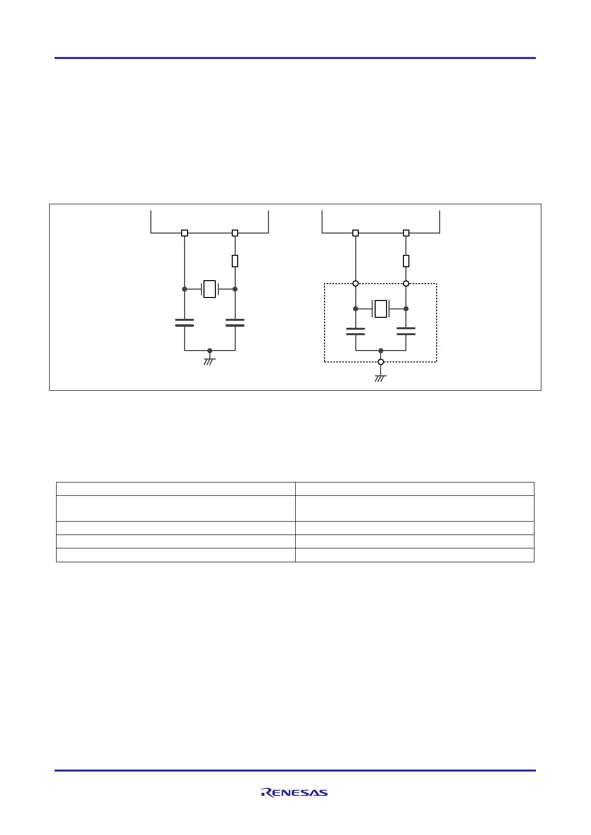
A crystal or ceramic resonator can be connected to the main clock input pins as shown below.
Figure 26: Recommended main oscillator circuit
General guidance values of the main oscillator circuit:
Table 58: Guidance values of the main oscillator circuit
RH850/F1Kx: 8MHz, 16MHz, 20MHz, 24MHz
RH850/F1K: 16MHz, 20MHz, 24MHz
Caution
Values of C1, C2, Rd and amplification gain selection controlled by MOSCC.MOSCAMPSEL[1:0] depend on
the use of ceramic or crystal resonator and must be specified in cooperation with ceramic or crystal resonator
manufacturer.
X1 X2
MOSC
C2C1
Rd
internal
external
X1
X2
MOSC
C2
C1
Rd
internal
external

 Loading...


