RH850/F1Kx, RH850/F1K Series Hardware Design Guide
R01AN3841ED0110 Rev. 1.10 Page 92 of 108
August 8, 2019
7. Device Operation Modes
The RH850/F1Kx series and RH850/F1K series support the following operation modes that are used for normal
operation, debugging, flash programming and test by using boundary scan.
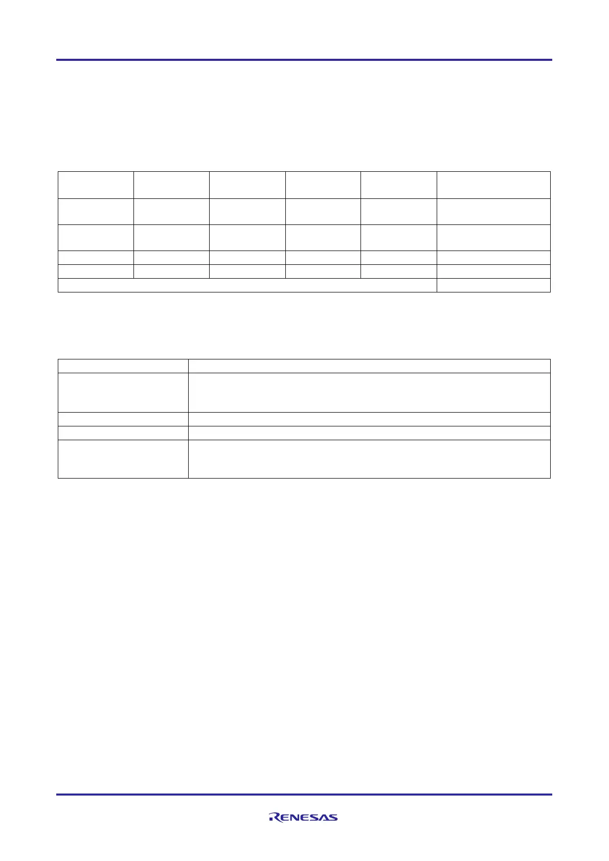
Table 68: Device operation mode overview
Note: x – Don’t care
Table 69: Device operation mode description
Mode used for the execution of application software and during debugging.
When FLMD0 is pulled-up to high-level during operation in this mode, writing
to the code flash memory by self-programming is enabled.
Mode used during the flash memory program/erase of the device.
Mode used for boundary scan test.
Mode used for the execution of application software and during debugging,
where the base address is fixed and the transition to stand-by modes is not
The related pins have to be configured accordingly on the PCB in order to define and support the required operation
modes.
Caution
To change the operating mode, restart from power-on clear reset (remove the power supply once and apply it
again). For details please refer to Sections 6, Operating Mode, 9A.1.1, Reset Sources and 9BC.1.1, Reset Sources
of the RH850/F1KH, RH850/F1KM Hardware User’s Manual or Sections 6, Operating Mode and 9.1.1, Reset
Sources of the RH850/F1K Hardware User’s Manual.

 Loading...


