RH850/F1Kx, RH850/F1K Series Hardware Design Guide
R01AN3841ED0110 Rev. 1.10 Page 23 of 108
August 8, 2019
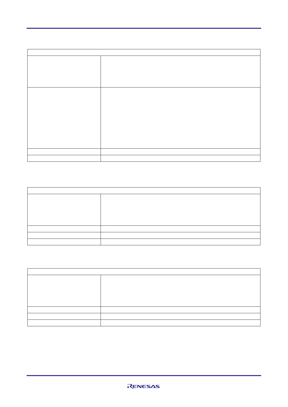
Table 17: RH850/F1KM-S4 Power supply architecture with mixed supply 5V & 3.3V
Case 8 – Mixed Supply 5V & 3.3V
EVCC = 5V
BVCC = 3.3V
A0VREF = 3.3V
AP0 – Port usable with analog or digital function
P8 – Port usable with analog or digital function, analog input
voltage limited to max. 3.3V. When analog input terminal is over 3.3V,
do not include the input into an AD scan group.
P9 – Port usable with analog or digital function, analog input
voltage limited to max. 3.3V. When analog input terminal is over 3.3V,
do not include the input into an AD scan group.
AP1 – Port usable with analog or digital function
P18 – Port usable with analog or digital function
P19 – Port usable with analog or digital function
Analog port function limitation applies to P8 and P9
Table 18: RH850/F1KM-S4 Power supply architecture with mixed supply 5V & 3.3V
Case 9, Case 10 – Mixed Supply 5V & 3.3V
EVCC = 3.3V or 5V
BVCC = don’t care
A0VREF = don’t care
Common condition REGVCC = EVCC not met
Table 19: RH850/F1KM-S4 Power supply architecture with mixed supply 5V & 3.3V
Case 11 – Mixed Supply 5V & 3.3V
EVCC = 3.3V
BVCC = 5V
A0VREF = don’t care
A1VREF = don’t care
Common condition REGVCC ≥ BVCC not met

 Loading...


