RH850/F1Kx, RH850/F1K Series Hardware Design Guide
R01AN3841ED0110 Rev. 1.10 Page 53 of 108
August 8, 2019
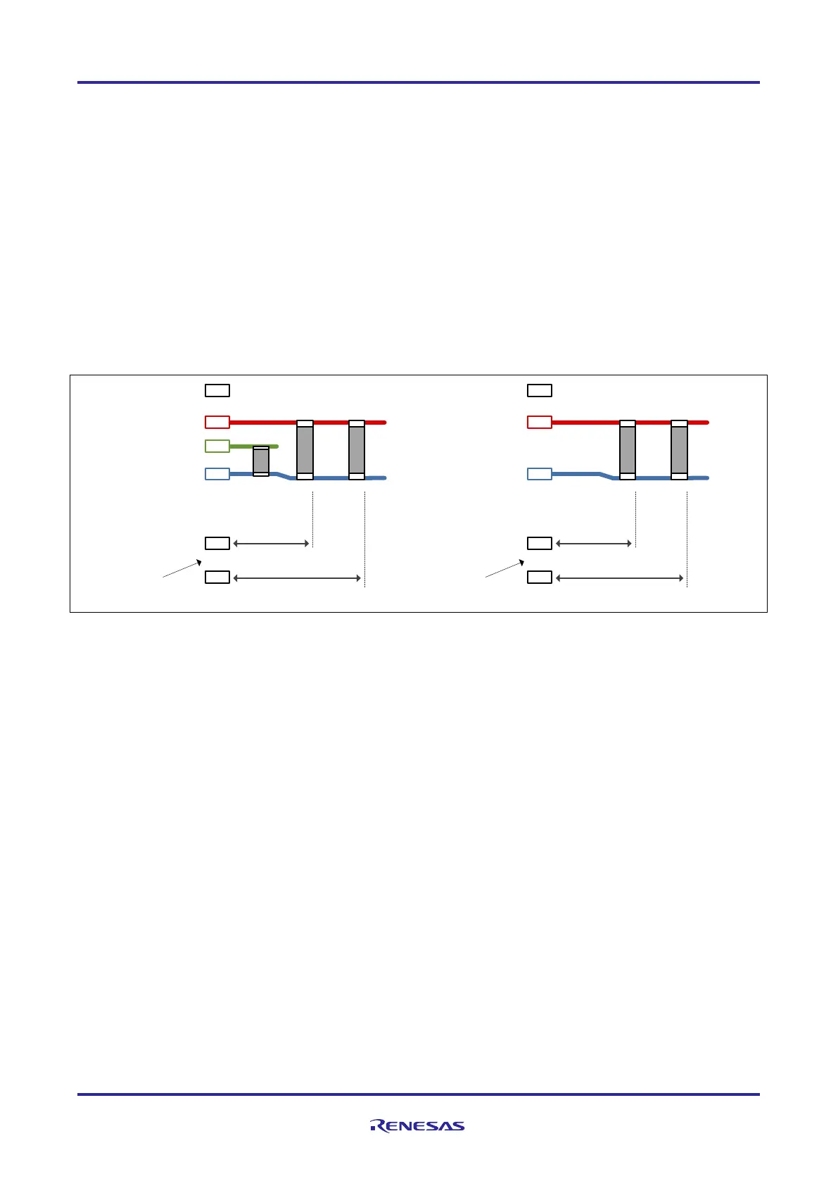
1.6 Principle Capacitor Placement at REGVCC of RH850/F1Kx, RH850/F1K Series
It should be considered to add an additional capacitor to the REGVCC pin and to use a close component placement to
the supply pin in order to optimize the EMI noise behavior especially during the program and erase operation.
The following recommendations shall be considered for the capacitor placement of the additional capacitor for EMI
optimization especially during the program and erase operation at the REGVCC pin:
• Capacitor: 4.7µF or larger
• Pin: REGVCC (F1KH-D8: REG0VCC, REG1VCC)
• Layout/distance: Capacitor within 10mm from mounting pad
Figure 21: Principle capacitor placement at REGVCC for EMI
Mounting pad
AWOVSS
AWOVCL
REGVCC
(REG0VCC)
0.1µF
fo r
AWOVCL
4.7µF or larger
fo r R E G VCC t o
optimize no ise
during Flash
P/W
As short as po ssible
(Recommendation: max. 4mm)
As short as po ssible
(Recommendation: max.10mm)
0.1µF
fo r
REGVCC
...
...
Mounting pad
ISOVSS
REG1VCC
4.7µF or larger
fo r R EG1V CC to
optimize no ise
during Flash
P/W
As short as po ssible
(Recommendation: max. 4mm)
As short as po ssible
(Recommendation: max.10mm)
0.1µF
fo r
REG1V CC
...
...

 Loading...


