RH850/F1Kx, RH850/F1K Series Hardware Design Guide
R01AN3841ED0110 Rev. 1.10 Page 71 of 108
August 8, 2019
4.2 RESET
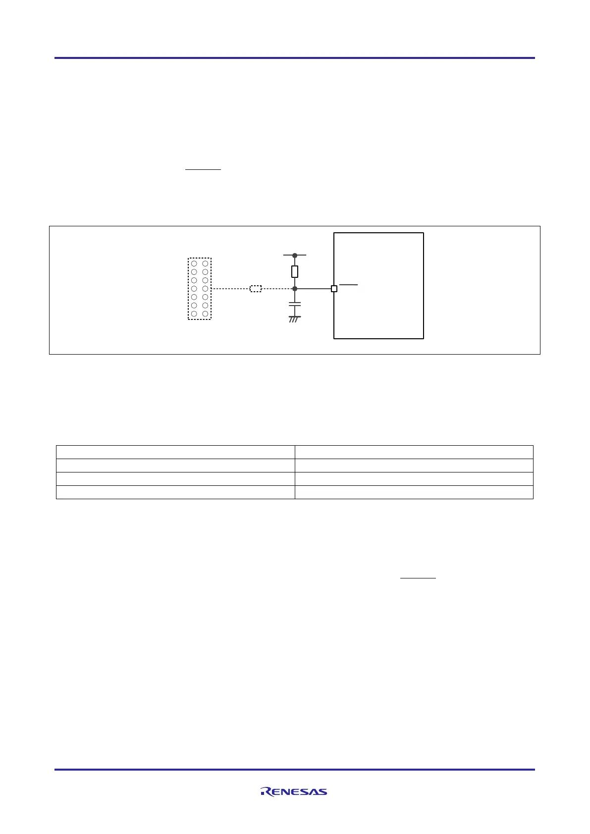
4.2.1 Minimum RESET Circuit
The RH850/F1Kx, RH850/F1K series has an on-chip Power-on Clear (POC) circuit. Therefore, a specific external
RESET circuit is not required and the minimum requirement of the RESET circuit is a resistor to EVCC for start-up of
the device. The resistor should be dimensioned large enough to allow a RESET signal generated by development tool or
flash programmer to control the
RESET pin.
In addition, a capacitor should be added as protection against surges.
Figure 29: Minimum RESET circuit
General guidance values of the minimum RESET circuit:
Table 60: Guidance values for the minimum RESET circuit
The series resistor R2 is optional to suppress external signals from EMC point of view and depends on the application
requirements.
The capacitor C1 can be adopted to a different value when the AC specification of the
RESET timing, the AC
specification of the flash programmer setup timing and the EMC requirements of the ECU are fulfilled.
RESET
EVCC
RH850/F1Kx
Development Tool,
Flash Programmer
R
1
C
1
R
2

 Loading...


