RH850/F1Kx, RH850/F1K Series Hardware Design Guide
R01AN3841ED0110 Rev. 1.10 Page 80 of 108
August 8, 2019
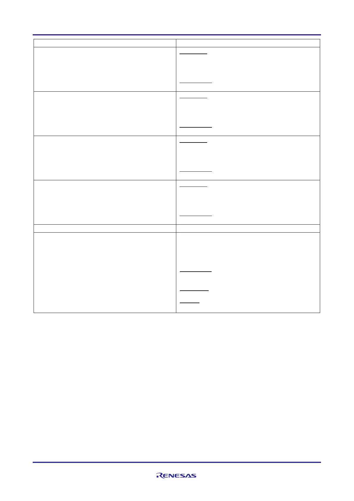
Recommended Connection of Unused Pin
P10_2
P10_6
P10_8
- Leave open (PIBCn_m = 0 and PMCn_m = 0)
- Connect to EVSS via resistor (PIBCn_m = 1 and
PMCn_m = 1)
Output state
- Leave open (PIBCn_m = 0)
- Connect to A0VREF or A0VSS via resistor
(PIBCn_m = 1)
Output state
- Leave open (PIBCn_m = 0)
- Connect to A1VREF or A1VSS via resistor
(PIBCn_m = 1)
Output state
JP0 (excluding JP0_4) – General-purpose I/O
Mode
- Leave open (PIBCn_m = 0 and PMCn_m = 0)
- Connect to EVCC or EVSS via resistor (PIBCn_m
= 1 and PMCn_m = 1)
Output state
JP0_4 – General-purpose I/O Mode
Connect to EVSS via a resistor
Note3
(LPD IF / Nexus IF)
Note2
DCUTDI/LPDI/LPDIO (JP0_0): Connect to EVCC
via a resistor
DCUTDO/LPDO (JP0_1): Leave open
DCUTCK/LPDCLK (JP0_2): Leave open
DCUTMS (JP0_3): Connect to EVCC via a resistor
DCUTRST
(JP0_4): Connect to EVSS via a
resistor
Note3
DCURDY
/LPDCLKOUT (JP0_5): Leave open
EVTO
(JP0_6): Leave open
Note1
The pin availability depends on the selected device.
This part describes the handling of JP0 debug port pins during operation mode when the debug
interface is not in operation. For details of the different interfaces, see Chapter 8, Development Tool
Interface.
When the Nexus interface is used for debugging the value of the resistor depends on the 3
rd
party
development tool specification.
XT1 = IP0_0 (XT2) = REGVCC or AWOVSS should be set.
XT1 is connected to IP0_0 (XT2) through an internal resistor. Therefore, it is necessary to maintain
an equal voltage level in order not to generate a current path.
Caution
When the debug mode is configured by OPBT0 on the RH850/F1KM-S4, the corresponding pins of the JP0 port
group are automatically switched to the selected debug interface. The remaining pins of JP0 can be used as
general-purpose I/O pin including its alternate function. Port usage details are described in the debug interface
connection chapter.

 Loading...


