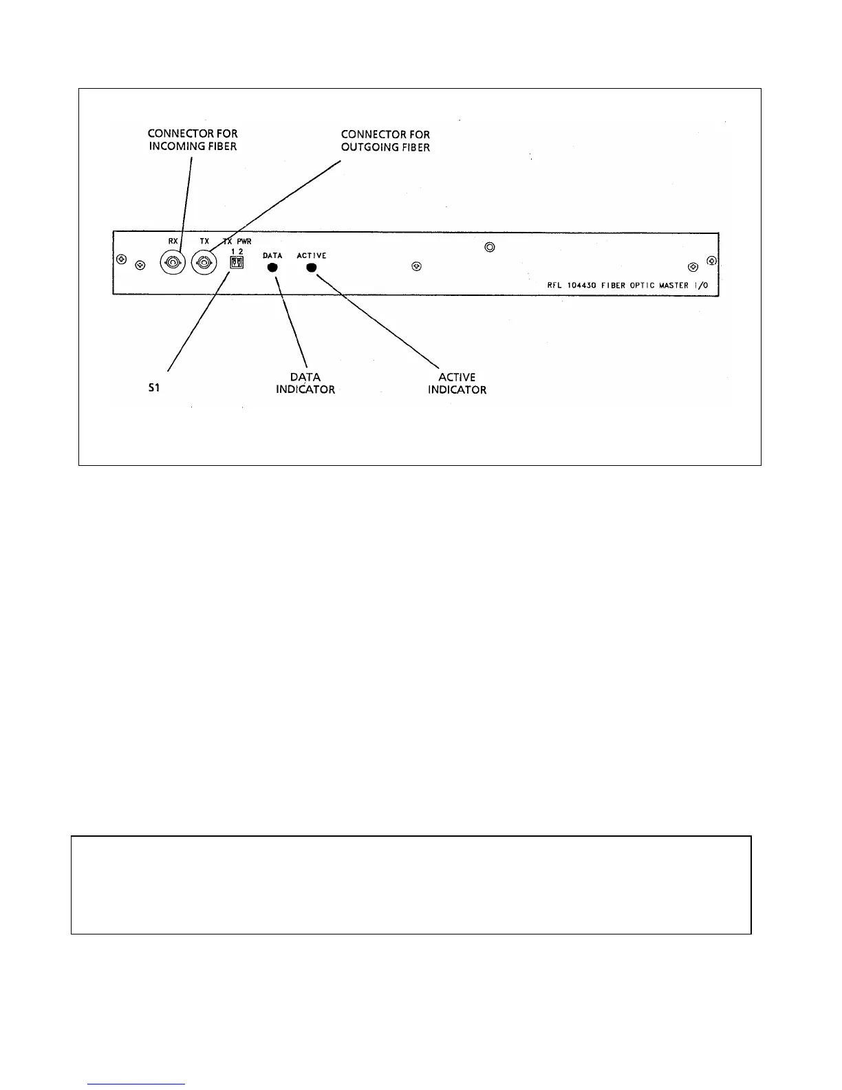
Figure 9-1. Programmable DIP switches and indicators, fiber optic master I/O module
DATA The DATA indicator lights when the fiber optic loop is running and the data being sent
is valid.
ACTIVE The ACTIVE indicator lights whenever a fiber optic port is being accessed.
RX The incoming fiber optic cable is connected to the RX connector.
TX The outgoing fiber optic cable is connected to the TX connector.
S1 TX PWR switch S1 controls the master I/O module's optical output power:
Output S1-1 S1-2
-42 dBm OFF (up) OFF (up)
-38 dBm ON (down) OFF (up)
-34 dBm OFF (up) ON (down)
-33 dBm ON (down) ON (down)
NOTE
These are typical power output levels when jumper J5 is in position ‘A’ (run mode), on Fiber Optic Master I/O
Module (Assembly No. 104430) as shown in the schematic of Figure 14-23 on page 14-55. Position ‘B’ (test
mode) is for factory use only.
RFL 9660 RFL Electronics Inc.
April 24, 2007 9-2 (973) 334-3100
 Loading...