1 2 3 4 5 6 7 8 9 10
11
RFL 9660
Digital Switch
STATUS
FIBER
LOOP
DATA DTR DCD FAIL ACC
REMOTE SET-UP
LOCAL 1 2 3 4
1
0
LOCAL
+5V
+15V
+15V
COM
ON
OFF
!
RFL 96 CCC
104410
RFL 96 MOD 24
104445
9125 125 DC
101970-3
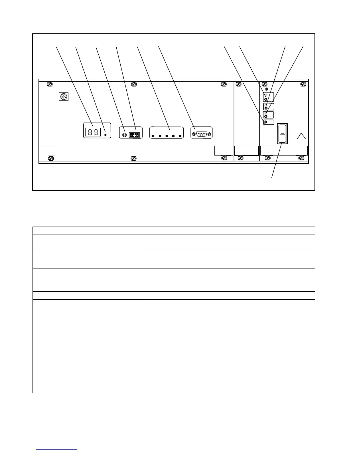
Figure 3-1. Controls and indicators, RFL 9660 Digital Switch
Table 3-1. Controls and indicators, RFL 9660 Digital Switch
Item Description or Marking Functional Description
1 STATUS display Displays two-character status messages. (See Section 7 for a list of code
displays.)
2 FIBER LOOP indicator Lights green when the fiber optic loop is installed and functioning properly; lights
red
when the fiber optic loop is not functioning properly.
3 REMOTE LOCAL switch 1. Disconnects the modem when in use.
2. Disconnects the selected switch port.
3. Initiates a master reset. (See pagefor procedure.)
4 SET-UP DIP switch Sets baud rate and parity for the local port. (See Sections 8 and 9.)
5 Switch status indicators Indicate RFL 9660 status:
DATA Lights green when RFL 9660 transmits and receives data.
DTR Lights green when modem is ready.
DCD Lights green when carrier is detected.
FAIL Lights red when RFL 9660 detects a failure.
ACC Lights green when the RFL 9660 is accessed.
6 LOCAL connector Connection port for local terminal.
7 COM test point Ground reference.
8 +5V test point and indicator Measuring point and monitor for +5-volt supply.
9 +15V test point and indicator Measuring point and monitor for +15-volt supply.
10 -15V test point and indicator Measuring point and monitor for -15-volt supply.
11 Switch, rocker Main power switch for RFL 9660.
RFL 9660 RFL Electronics Inc.
October 1, 1999 3-2 (973) 334-3100