2.5.5 CONNECTIONS TO DIRECT DIGITAL INTERFACE
If your RFL 9660 is equipped with a direct digital interface I/O module (Part Number 104455) instead of a
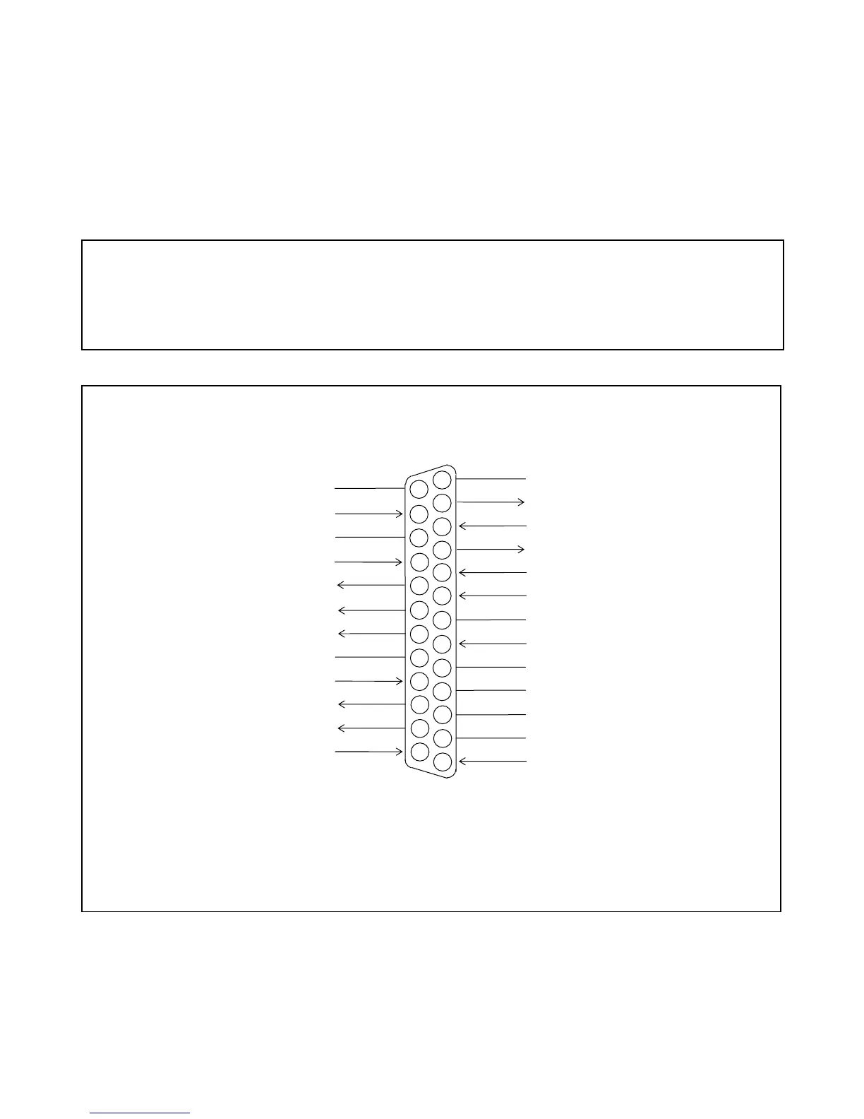
modem module and telephone interface module, there will be a 25-pin D-subminiature connector (DB-25 male)
on the rear panel. A cable must be connected between this connector and the local DTE. The DTE can be either
an external modem or a communications network multiplexer. Pin assignments for this connector are shown in
Figure 2-7.
NOTE
Unless specified at time of order, the direct digital interface port is set for 2400 baud, eight data bits,
one stop bit, and no parity. If the DTE or modem you are connecting to requires a different setting, go
to Section 8 and reset DIP switch S3 on the CPU module before attempting to use the RFL 9660.
NOTE: Shielded cable should be used. Length must not exceed 250 feet (75 meters).
6
1
2
3
4
5
7
8
9
CHASSIS GROUND
TRANSMIT DATA (TxD)
RECEIVE DATA (RxD)
REQUEST-TO-SEND (RTS)
CLEAR-TO-SEND (CTS)
DATA SET READY (DSR)
SIGNAL COMMON
DATA CARRIER DETECT (DCD)
NOT USED
NOT USED
NOT USED
DATA SIGNAL RATE SELECTOR
NOT USED
NOT USED
TX SIGNAL ELEMENT TIMING (DCE)
NOT USED
RX SIGNAL ELEMENT TIMING (DCE)
LOCAL LOOPBACK
REMOTE LOOPBACK
DATA TERMINAL READY (DTR)
INTERNALLY TIED TO PIN 19
RING INDICATOR
DATA SIGNAL RATE SELECTOR
TX SIGNAL ELEMENT TIMING (DTE)
TEST MODE
DB-25 CONNECTOR (MALE)
10
11
12
13
14
15
16
17
18
19
20
21
22
23
24
25
Figure 2-7. Terminal assignments for direct digital connector on RFL 9660 Digital Switch
RFL 9660 RFL Electronics Inc.
April 24, 2007 2-9 (973) 334-3100