2.3 MOUNTING
After unpacking, the RFL 9660 must be securely mounted. The RFL 9660 chassis has two mounting ears (one
on each side). Hole sizes and spacings conform with EIA standards, so the RFL 9660 can be mounted in any
standard 19-inch rack or cabinet. Figure 2-2 provides complete mounting dimensions.
2.4 VENTILATION
The specified operating temperature range for RFL 9660 equipment is -30
o
C to +65
o
C (-22
o
F to +149
o
F).
Operation at higher temperatures may affect system reliability and performance. Systems installed in enclosed
cabinets should be ventilated to keep the temperature inside the cabinet within limits.
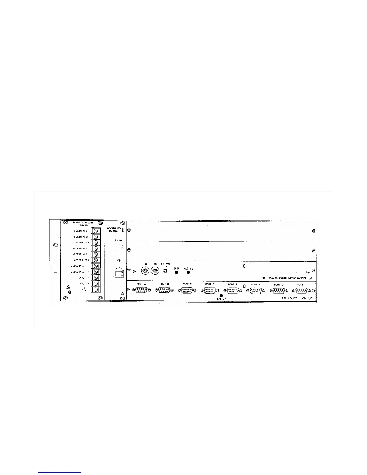
2.5 CONNECTIONS
Electrical connections are made to the RFL 9660 through the terminal blocks and connectors on its rear-panel
I/O modules. (See Figure 2-1.) The following paragraphs provide basic descriptions of all the connections that
must be made.
Figure 2-1. Rear view of typical RFL 9660 Digital Switch
2.5.1 MAKING CONNECTIONS TO TERMINAL BLOCKS
The terminal blocks on the RFL 9660's rear-panel I/O modules are conventional screw-type barrier blocks.
Depending on local practice, you can either strip the wires you connect to them, or terminate the wires in spade
lugs.
RFL 9660 RFL Electronics Inc.
April 24, 2007 2-2 (973) 334-3100