9.3 FIBER OPTIC REMOTE MODULE
Each fiber optic remote module has two programmable DIP switches, three LED indicators, two fiber optic cable
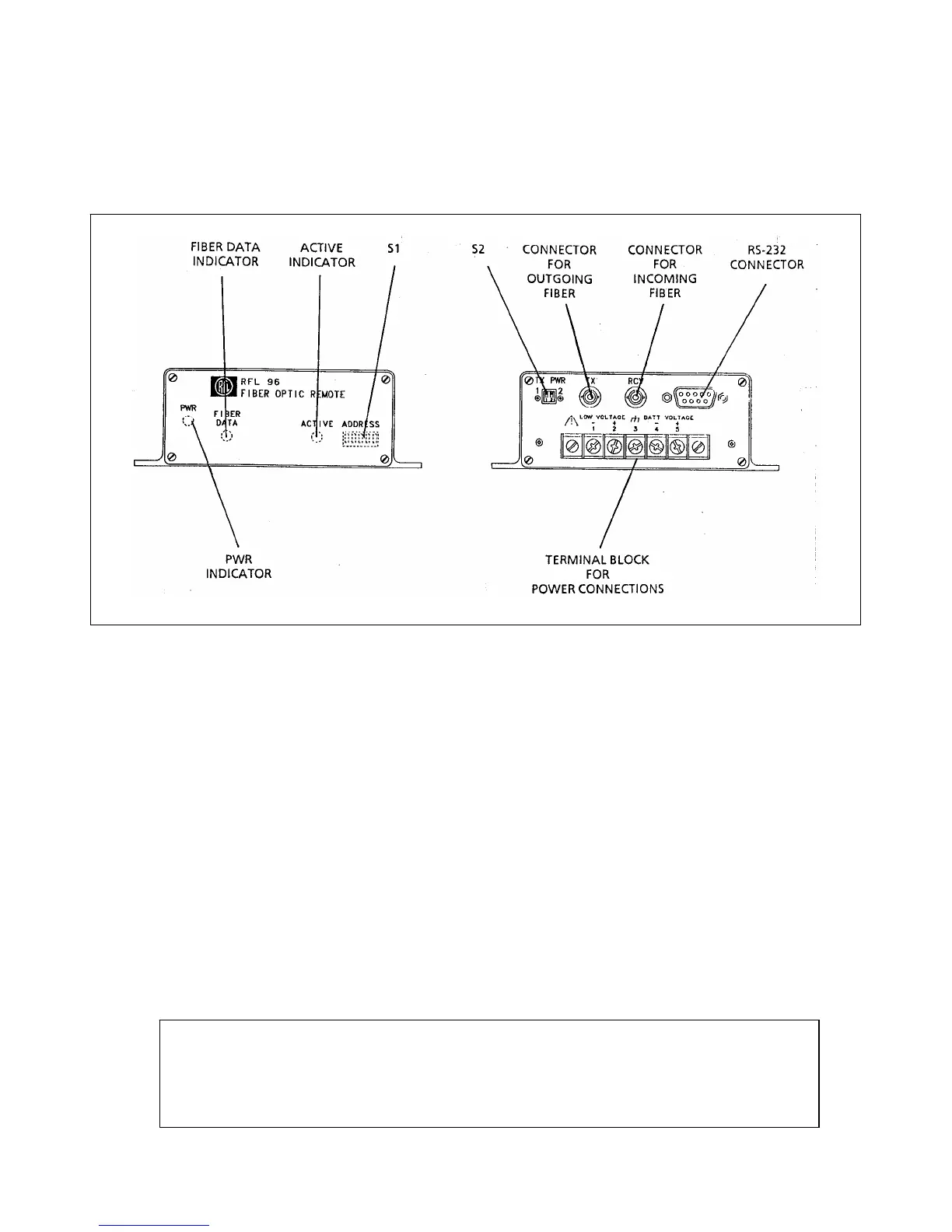
connectors, a 9-pin RS-232 connector, and a five-position terminal block. Figure 9-2 shows the location of these
items.
Figure 9-2. Programmable DIP switches and indicators, fiber optic remote module
ACTIVE The ACTIVE indicator lights when the device connected to the RS-232 connector is being
accessed by the RFL 9660.
FIBER DATA The FIBER DATA indicator lights when loop integrity is good at the remote module and the data
being received is valid.
PWR The PWR indicator lights when dc input power is being applied to the remote module.
S1 ADDRESS switch S1 sets the remote module's address. It sets up a binary number that
represents the port number assigned to the device. (See Table 9-1.)
S2 TX PWR switch S2 controls the remote module's optical output power:
Output S2-1 S2-2
-42 dBm OFF (up) OFF (up)
-38 dBm ON (down) OFF (up)
-34 dBm OFF (up) ON (down)
-33 dBm ON (down) ON (down)
NOTE
These are typical power output levels when jumper J1 is in position ‘A’ (run mode), on Fiber
Optic Remote Module (Assembly No. 104460) as shown in the schematic of Figure 14-27
on page 14-65. Position ‘B’ (test mode) is for factory use only.
RFL 9660 RFL Electronics Inc.
April 24, 2007 9-3 (973) 334-3100