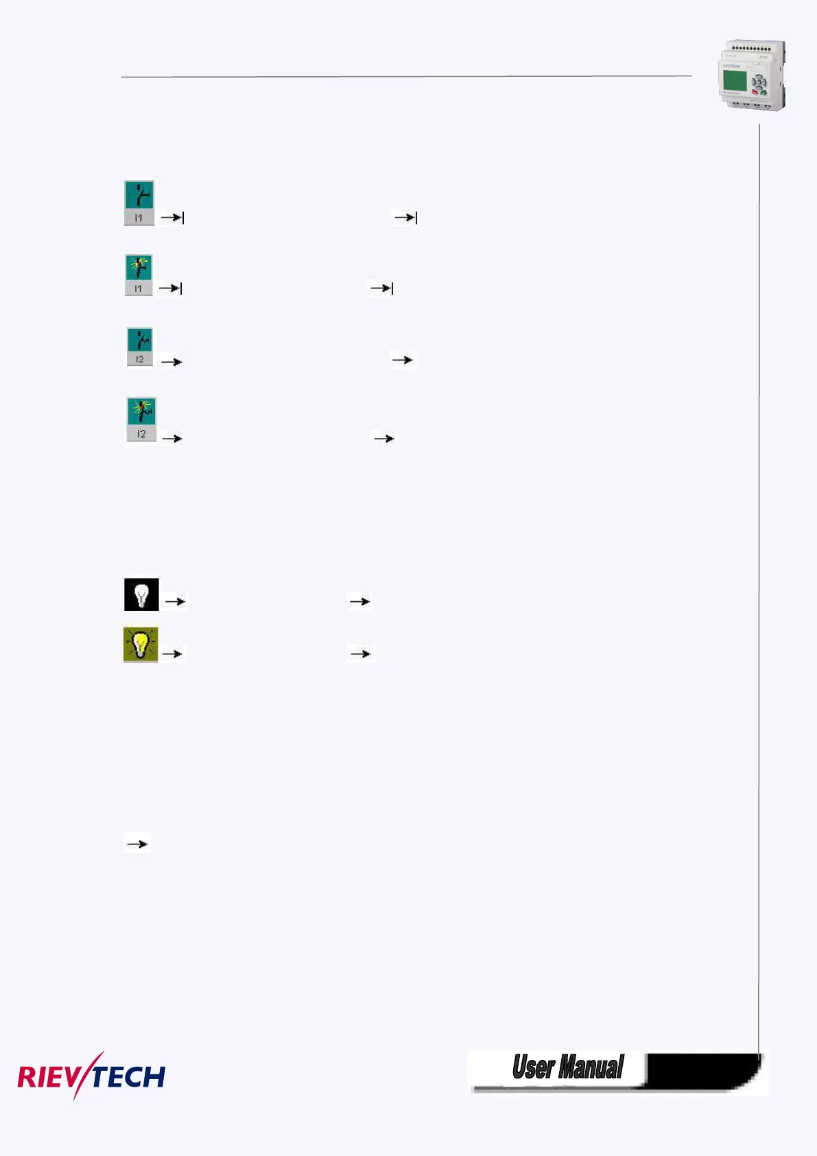
The inputs are displayed in the form of key or switch icons. The name of the input is displayed below the
icon. An open input represents an inactive switch. When you click on the icon, it is indicated active and
the switch is shown in closed state.
Icon for pushbutton I1, not actuated open input
Icon for pushbutton I1, actuated closed input
Icon for pushbutton I2, not actuated open input
Icon for pushbutton I2, actuated closed input
Layout of the outputs
The status of an output is indicated by a light or dark bulb icon. The name of the output in your circuit
program is displayed below this icon.
Status display of output Q1 Output switched off
Status display of output Q1 Output switched on
The output status only indicates the status as such. Here, you cannot switch an output by clicking on an
icon. When your circuit program switches an output, the indicator lamp is active; when the output is
switched off, the indicator lamp is also switched off.
Prerequisite: The display of signal states and process variables is enabled under Tools
Simulation.
The colored indication lets you identify the "1" or "0" status of a connecting line. Default color of
connecting lines carrying a "1" signal is red. Default color of connecting lines carrying a "0" signal is blue.