No. Name Description
4 USB HOST
Connect the instrument (as "host" device)
to external USB device (such as USB
storage device); extend a GPIB interface
for the power supply using the USB-GPIB
interface module (optional).
5 CH3 CH3 output terminal ports
6 AC selector
Select the specification of the input
voltage: 100, 120, 220, or 230 (please
refer to
Connecting to Power
).
7 AC power inlet socket AC inlet power connector
8 Fuse
The fuse rating is related to the
instrument model and actual input
voltage (please refer to
Replacing the
Fuse
).
9
AC input power
requirement
The table describes the relationship
between the frequency, voltage of the
input power and fuse rating.
10 Ground terminal -
11 Fan ventilation hole -
12 CH1 and CH2 CH1&CH2 output terminal ports
13
RS232/GPIB port
[1]
Available for RS232 or GPIB interface
(optional)
Note[1]: DP2000 series provides RS232 (standard) and GPIB (optional). Sharing a
physical port, those two interfaces cannot be used concurrently.
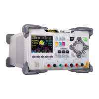
4.5 User Interface
Tap > Display to assess the interface as shown in the figure below. This section
introduces the meter-view display of the power supply.
Quick Start
Copyright ©RIGOL TECHNOLOGIES CO., LTD. All rights reserved.
DP2000 User Guide
17