11
Trigger
DP2000 series power supply supports trigger input and trigger output via the rear-
panel Digital I/O interface.
• Trigger Input:
The data lines of the digital I/O interface receive external trigger signal. The
source under control (namely the selected output channel) turns on/off the
output or inverts the output state when the preset trigger condition is met.
• Trigger Output:
The data lines of the digital I/O interface output a high/low level signal when the
control source (namely the selected output channel) turns on the output.
The 4 data lines of the digital I/O interface are mutually independent and can be used
for trigger input or trigger output separately.
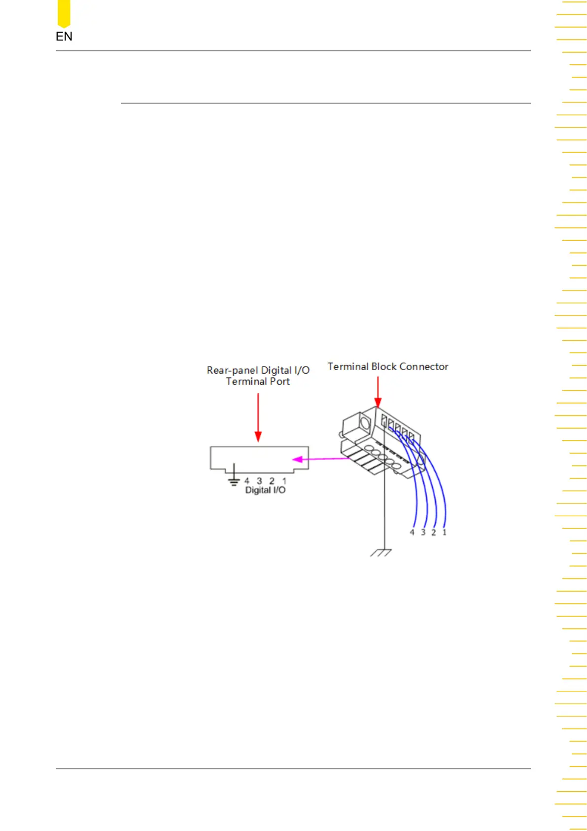
The digital port connections are shown in the figure below.
Figure 11.1 Digital Port Connections
Operation Procedures:
1. Connect the wires to the terminal block connector according to the figure above
(pay attention to the corresponding relations).
2. Insert the terminal block connector into the digital I/O terminal port on the rear
panel (pay attention to the corresponding relations).
Trigger
Copyright ©RIGOL TECHNOLOGIES CO., LTD. All rights reserved.
DP2000 User Guide
55