No. Description
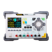
8 Voltage setting value
9 Over-voltage protection (OVP) status indicator, indicating the
present OVP on/off state
10 Current setting value
11 Over-current protection (OCP) status indicator, indicating the
present OCP on/off state
12
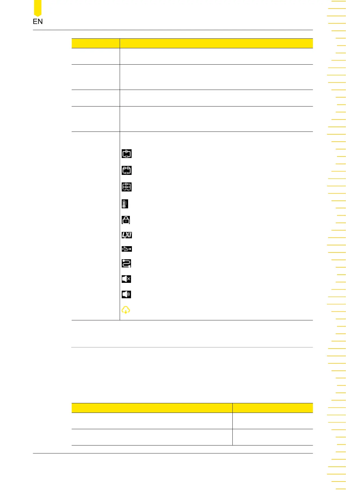
The following icons indicate the system status.
: CH1 and CH2 are independent of each other.
: CH1 and CH2 are connected in series.
: CH1 and CH2 are connected in parallel.
: over-temperature protection is tripped.
: the screen is locked.
: network connected.
: a USB device is detected.
: the instrument is in remote control.
: the beeper is turned off.
: the beeper is turned on.
: downloading the firmware upgrade file.
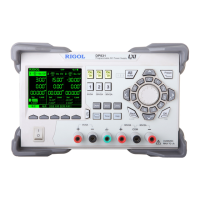
4.6 Connecting to Power
DP2000 series power supply supports various AC power inputs. The AC selector
setting on the rear panel differs when input power is different, as shown in the table
below.
Table 4.3 AC input power specifications (including AC selector setting)
AC input power AC selector
100 Vac±10%, 50 Hz to 60 Hz 100
120 Vac±10%, 50 Hz to 60 Hz 120
Quick Start
Copyright ©RIGOL TECHNOLOGIES CO., LTD. All rights reserved.
DP2000 User Guide
19