2. Set proper voltage, current, and over-current protection value for each channel
(refer to
Constant Voltage Output
) and turn on the channel outputs. All the
channels connected in series should be set to CV mode and have identical current
setting value and OCP value.
CAUTION
Please make sure that all the channels connected in series operate in CV mode. One of the
channels operating in CC mode can cause unregulated output mode for the other
channels.
8.2 Parallel Connections
Connecting outputs in parallel provides a greater current capability than can be
obtained from a single output. The total current is the sum of the individual currents
of all channels connected in parallel. To connect outputs in parallel externally, you
need to ensure identical voltage value and OVP value for each channel.
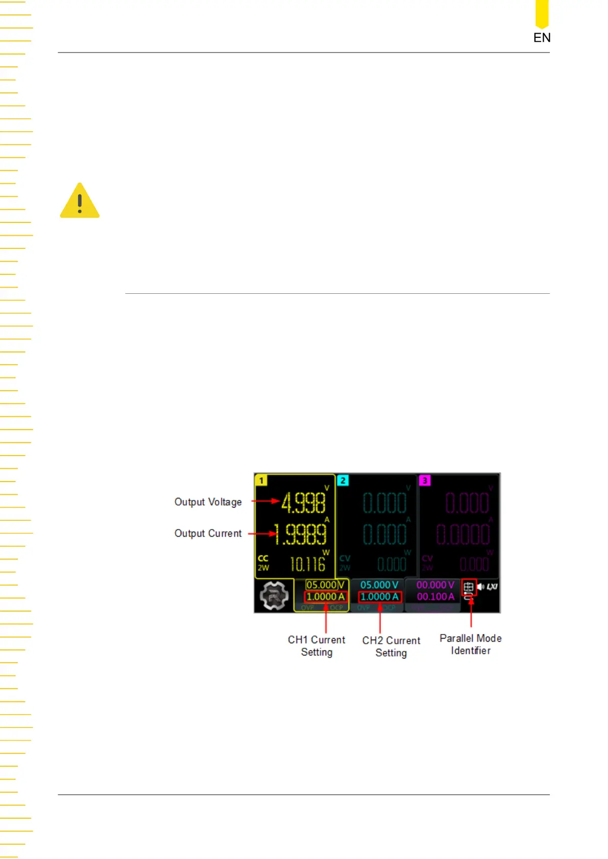
Internal Parallel Connections
This series power supply supports internal parallel connection for CH1 and CH2. In
internal parallel connection mode, the output current (up to 6 A) is twice the current
setting. The output voltage and current are displayed in CH1 meter view, as is shown
in the figure below.
Figure 8.3 Parallel Output Interface
The figure below shows how to connect front output terminals to a single load in
internal parallel mode. Please refer to
Output Connection
for channel connection.
Series/Parallel Connections
DP2000 User Guide
34
Copyright ©RIGOL TECHNOLOGIES CO., LTD. All rights reserved.