Wrist Camera Instruction Manual
3.5. Electrical Setup
3.5.1. Power Supply
Caution
If mounting a 2-Finger Gripper on the Wrist Camera, the Camera replaces the gripper's coupling. Therefore,
only the Wrist Camera's device cable is required to provide power and communication to both the camera
and the gripper. The wiring for setups including only the camera or both the camera and the gripper is the
same.
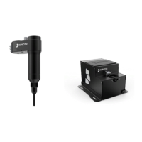
Power and communication are established with the Wrist Camera via the high-flex device cable. The cable provides a
24V power supply to the Wrist Camera and enables USB 2.0 communication with the Universal Robots controller.
Follow these steps to correctly wire the Wrist Camera (or the camera and 2-Finger Gripper combo) to a Universal
Robots controller :
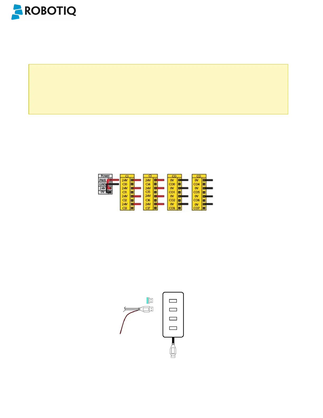
l With the controller turned off, connect the red (24V) and black (0V) wires of the device cable as shown in the figure
below. Use any available 24V and0V.
Fig. 3-3: Power supply wiring on CB3.1 Universal Robots controller.
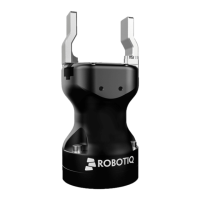
l Connect the 4-port USB hub (ACC-USB-4-HUB) inside the robot controller.
l Connect the Wrist Camera's USB connector in the 4-port USB hub.
l Connect the license USB dongle (ACC-USB-DONGLE) in the 4-port USB hub.
Fig. 3-4: 4-port USB hub connection.
©Robotiq inc. 2016-2018
21