EasyManuals Logo

Rockwell Automation Allen-Bradley 1715-IF16 User Manual

Rockwell Automation Allen-Bradley 1715-IF16
298 pages
To Next Page IconTo Next Page
To Previous Page IconTo Previous Page
Page #113 background imageLoading...
Page #113 background image
Rockwell Automation Publication 1715-UM001J-EN-P - December 2020 113
Chapter 2 Installation Instructions
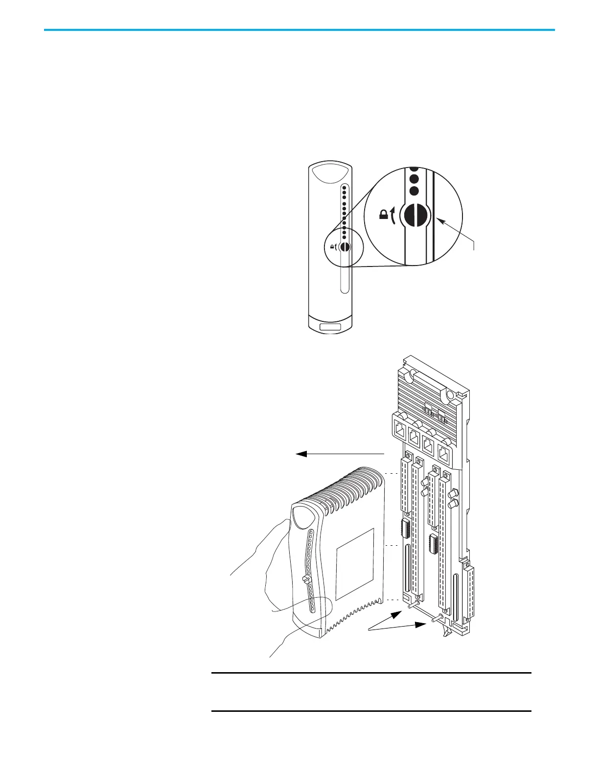
Remove modules by carefully pulling them out of the base unit by using this
procedure.
1. Turn the locking screw on the front of the module 1/4 turn counter-
clockwise.
The screw slot is vertical when the module is unlocked.
2. Carefully remove the module from the base unit.
IMPORTANT
Make sure that you pull the module straight out when removing it
from the base unit. Do not rock, or tilt the module while pulling it
out, as it could damage the dowel pins.
Unlocked Position
Turn locking screw 1/4 turn
counter-clockwise until
vertical.
32084 M
45237
Pull straight out.
Dowel Pins

Table of Contents

Questions and Answers:

Question and Answer IconNeed help?

Do you have a question about the Rockwell Automation Allen-Bradley 1715-IF16 and is the answer not in the manual?

Rockwell Automation Allen-Bradley 1715-IF16 Specifications

General IconGeneral
BrandRockwell Automation
ModelAllen-Bradley 1715-IF16
CategoryI/O Systems
LanguageEnglish

Related product manuals