Rockwell Automation Publication 1715-UM001J-EN-P - December 2020 285
Appendix F I/O Tag Definitions
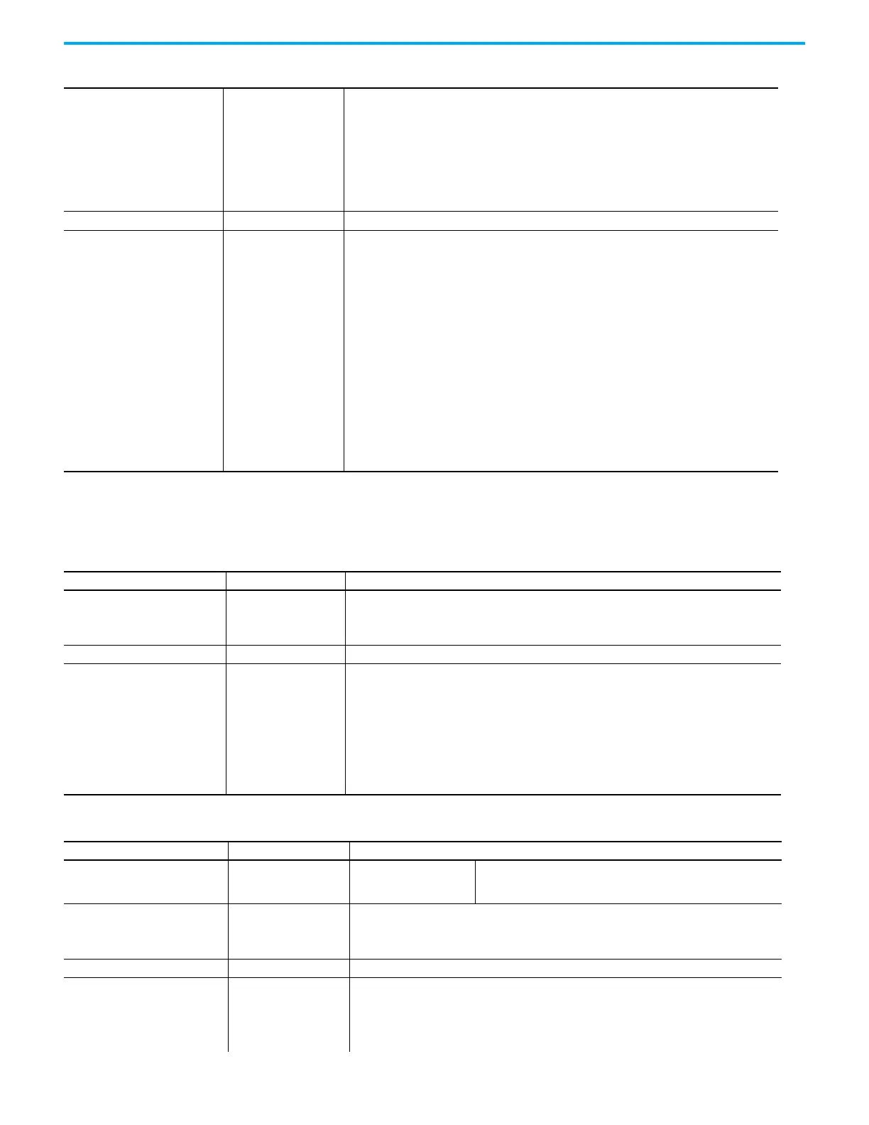
1715-OF8I This section describes the tags that are associated with the 1715-OF8I module.
1 = This channel on Module B is
faulted/failed
3 Underrange 0 = Good
1 = Underrange detected
4 Overrange 0 = Good
1 = Overrange detected
RollingTimestamp INT Timestamp data
Status DINT, bit-field Bit Name Description
0 ModAFault 0 = Good
1 = Fault or module not present
1 ModBFault 0 = Good
1 = Fault or module not present
8 GroupFault 0 = Good
1 = Any channel on module is faulted/
failed
9 ModAGroupFault 0 = Good
1 = Any channel on Module A is
faulted/failed
10 ModBGroupFault 0 = Good
1 = Any channel on ModuleB is faulted/
failed
Table 70 - 16-channel Analog Input, Duplex, Input
Tag Name Data Type Definition
Table 71 - 8-channel Analog Output, Output
Tag Name Data Type Definition
AOCh[0…7] Array of structure Array of 8 structures for the output data:
0 = Data
1 = Faults
Data REAL Commanded output value
Control DINT, bit-field Alarm control:
Bit Name Description
0 HAlarmUnlatch
Rising edge transition (that is, 0 > 1)
unlatches alarm
1 LAlarmUnlatch
Rising edge transition (that is, 0 > 1)
unlatches alarm
2 RateAlarmUnlatch
Rising edge transition (that is, 0 > 1)
unlatches alarm
Table 72 - 8-channel Analog Output, Simplex, Input
Tag Name Data Type Definition
Fault DINT, Binary Module fault bit:
0 when a module is present and reporting valid data, OxFFF_FFFF
when no module is present, no Logix connection exits, or reported
data is invalid.
ChDuplex[0…7] Array of structure Array of 8 structures that represent the data and fault status for channels 0…7:
0 = Data
1 = Faults
ReadBack REAL Input data
Faults DINT, bit-field Channel fault status:
Bit Name Description
0Fault0 = Good
1 = Circuit fault for this channel
 Loading...


