86 Rockwell Automation Publication 1715-UM001J-EN-P - December 2020
Chapter 2 Installation Instructions
To avoid spurious declaration of channel faults, it is necessary to ensure that
the field supply voltage and output signal condition satisfies the maximum
slew rate criteria that are defined in the 1715 Redundant I/O System
Specifications Technical Data, publication 1715-TD001
.
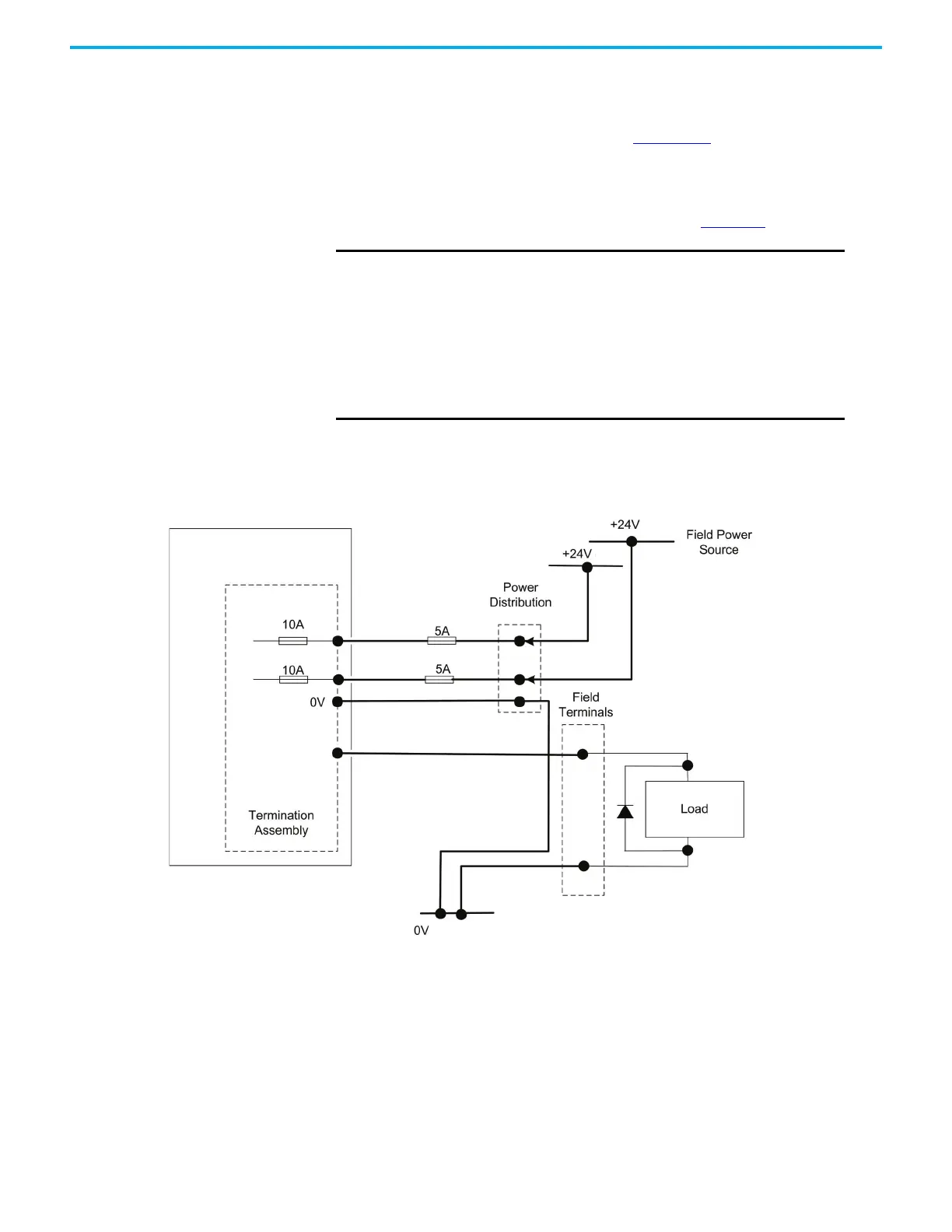
Field Loop Circuits for Digital Outputs
The field loop circuit for a digital output is shown in Figure 44.
Figure 44 - Digital Output (Simplex or Duplex) Field Loop Circuit
Recommended Circuits for Analog Inputs
This section describes the layout for analog inputs.
IMPORTANT
The field power 5A fuses comply with UL508 requirements. The
5A fuses are No. 396/TE5 5A time lag fuse; UL 248-14, 125 V,T
Leadfree; manufactured by Littelfuse.
• You can use Class 2 power supplies for the +24V DC field voltage
instead of the two 5A fuses. The NEC defines Class 2 as providing
less than 100 watts (at 24V).
• When digital output modules are configured as a redundant pair,
the minimum load current that is required for channels with line
monitoring is 20 mA.
33002 M
Important: For inductive loads, a back EMF protection diode is fitted at the load.
 Loading...


