Rockwell Automation Publication 1715-UM001J-EN-P - December 2020 25
Chapter 1 Redundancy System Overview
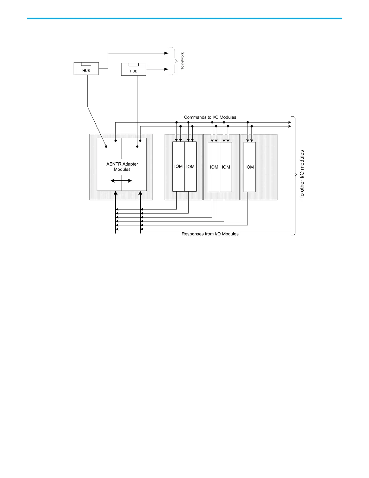
Figure 9 - Bus Diagram of 1715 Redundant I/O System
Switchover Considerations Each 1715 Redundant I/O System uses one IP address as the primary IP address
for all communication on the EtherNet/IP network. The redundant adapter
pair consists of two active modules, a primary adapter and its partner, a
secondary module. For this document, the primary module is referred to as
module ‘A’ and the secondary module is referred to as module ‘B’.
On power-up, the adapter in the leftmost slot is considered the primary
module (when two adapters are present) because it uses the primary IP
address, and because it is the module responsible for receiving/transmitting to
ControlLogix controller on the EtherNet/IP network.
The module in the rightmost slot is considered the secondary module partner
and uses the primary IP address +1. For example, if the primary module in the
leftmost slot has an IP address of ‘N’, then the secondary module in the
rightmost slot, has an IP address of ‘N+1’.
Both modules are always active and are responsible for monitoring all inputs
and outputs, monitoring diagnostics in the system, and reading and writing
data from/to I/O simultaneously. When the primary module receives a write, it
notifies the secondary module of the data to write and which module to write it
to. At a synchronized point in time, both adapters physically write to the I/O.
 Loading...


