72 Rockwell Automation Publication 1715-UM001J-EN-P - December 2020
Chapter 2 Installation Instructions
Wire the Adapter The 1715 adapter base unit has a series of screw terminal blocks to terminate
power connections to ease cable installation.
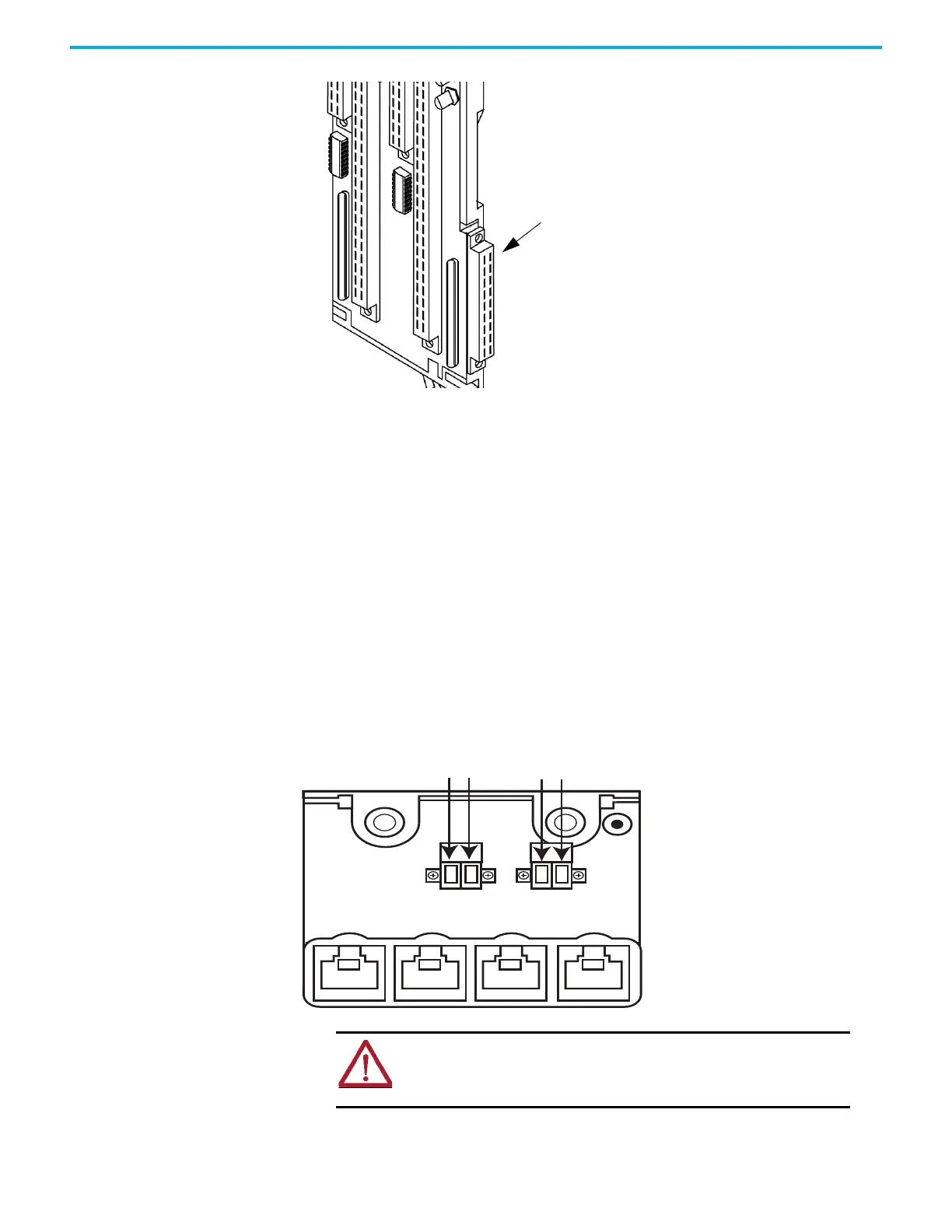
Connect the 24V DC System Power
The 1715 modules are designed to operate from two independent 24V DC
sources with a common return. Power is connected to the two plugs, ‘PWR-1’
and ‘PWR-2’ on the adapter base plate. Power is distributed to the I/O modules
through the base units.
Figure 28 - Connect System Power
32060 M
Connect cable plug assembly to
the adapter base connector.
Adapter Base Connector
Pwr1
Pwr2
+24V DC
+24V DC
C
o
m
m
o
n
C
o
m
m
o
n
ATTENTION: To comply with the CE Low Voltage Directive (LVD), all
connections to this equipment must be powered from a source
compliant with safety extra low voltage (SELV) or protected extra low
voltage (PELV)
 Loading...


