96 Rockwell Automation Publication 1715-UM001J-EN-P - December 2020
Chapter 2 Installation Instructions
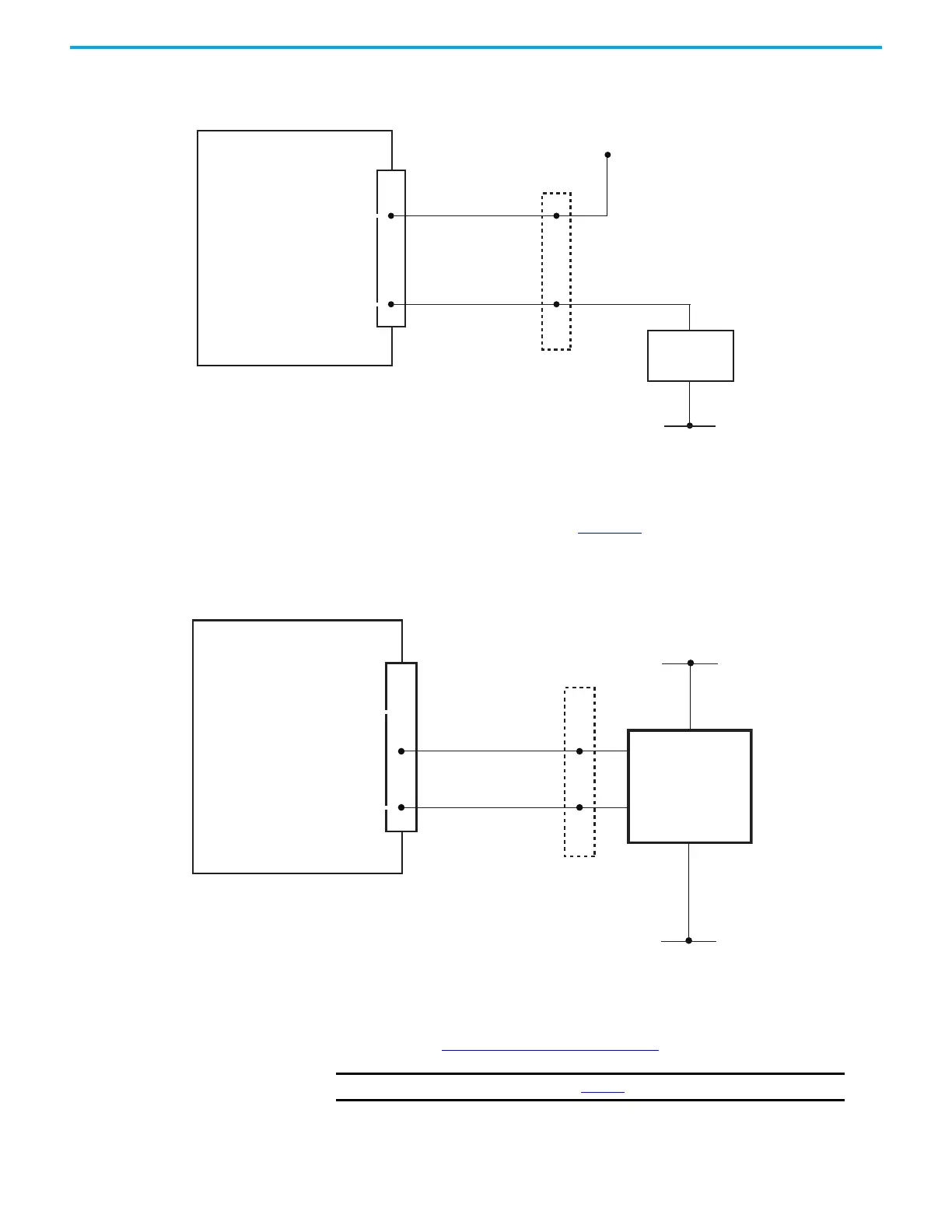
Figure 56 - 1715-OF8I Analog Output Module Recommended Field Loop Circuit Field Power Circuit
Field Power Circuit for Analog Outputs
An alternative method is shown in Figure 57. The figure shows when the field
power is used to supply the load.
Figure 57 - Field Power Circuit for Analog Outputs
Connect the Adapter to the
Ethernet Network
The adapter supports DLR (Ring) and Star topologies. For more details on
topologies, see System Architecture on page 16
.
System
+24V DC
OV
Termination
Assembly
Analog Output
Module
CH+
CH-
Load
Field
+24V DC
OV
Termination
Assembly
Analog Output
Module
CH+
CH-
Load
IMPORTANT
For wiring details, see Table 11.
 Loading...


