Rockwell Automation Publication 1715-UM001J-EN-P - December 2020 217
Chapter 7 1715 Redundant I/O System in SIL 2 Safety Applications
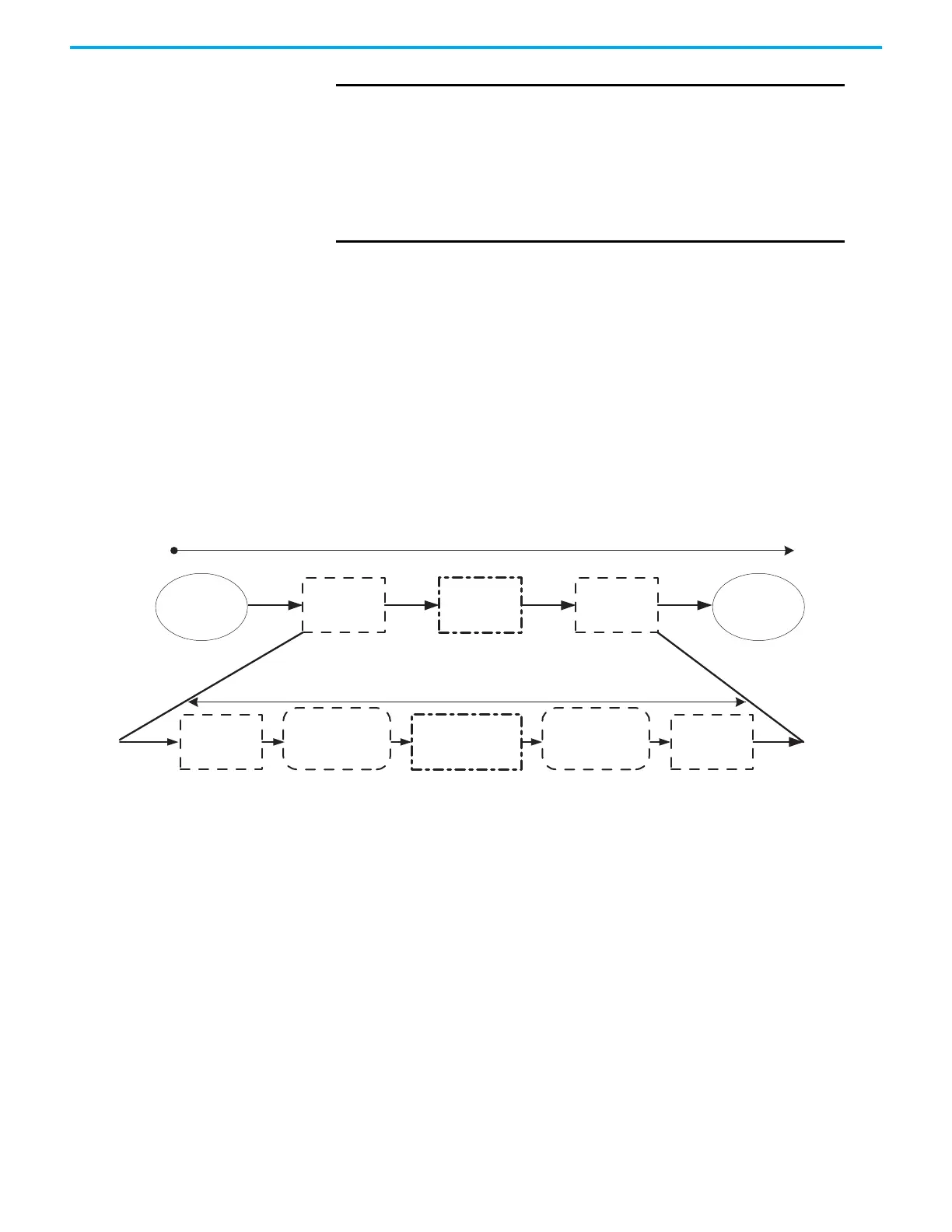
Reaction Times To determine the system reaction time of any control chain, you must add up
the reaction times of all of components of the safety chain.
System Reaction Time
System Reaction Time = Sensor Reaction Time + Logix System Reaction Time
+ Actuator Reaction Time
Figure 67 - System Reaction Time
Logix System Reaction Time
The following sections provide information on calculating the Logix System
Reaction Time for a simple input-logic-output chain and for a more complex
application using produced/consumed safety tags in the logic chain.
IMPORTANT
The Reset Counters button on the diagnostics tab resets only the
counters that are shown in the 1715 I/O module profiles.
It does not reset the counters that are displayed within the
ControlLogix Add-On Instructions.
The values retrieved from 1715 output modules populate the
diagnostic information. Equivalent input module diagnostic data
is made available by the
Add-On Instructions.
System Reaction Time
Sensor Reaction
Time
Input Reaction
Time
Safety Task
Reaction Time
Output Reaction
Time
Actuator Reaction
Time
Input Module
Delay
Input Connection
Reaction Time Limit
Safety Task Period
+
Safety Task Watchdog
Output Connection
Reaction Time Limit
Output Module
Delay
 Loading...


