Rockwell Automation Publication 1715-UM001J-EN-P - December 2020 43
Chapter 2 Installation Instructions
Figure 17 - Fuse Tags
The F2 and F4 fusing faults of the 1715 I/O modules cannot be pinpointed. All
healthy I/O module status indicators showing solid red indicates a blown F2 or
F4 fuse.
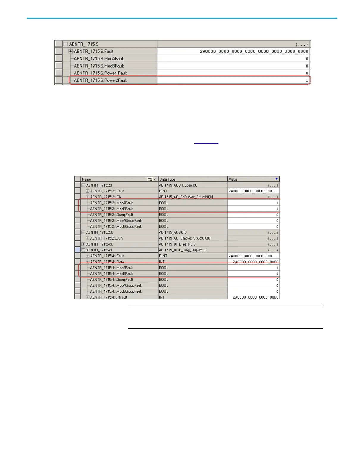
The adapter tags indicate each individual I/O module tag, ModAFault and
ModBFault, as shown in Figure 18
.
Figure 18 - Adapter Tags Indicate Faults
1715-A3IO I/O Base Unit
The I/O base unit holds up to three I/O modules.
IMPORTANT
After any fuse replacement or power-related issue on PWR-1/
PWR-2, the Reset button on the 1715-AENTR must be pressed to
clear the fault and reset the status indicator back to solid green.
 Loading...


