82 Rockwell Automation Publication 1715-UM001J-EN-P - December 2020
Chapter 2 Installation Instructions
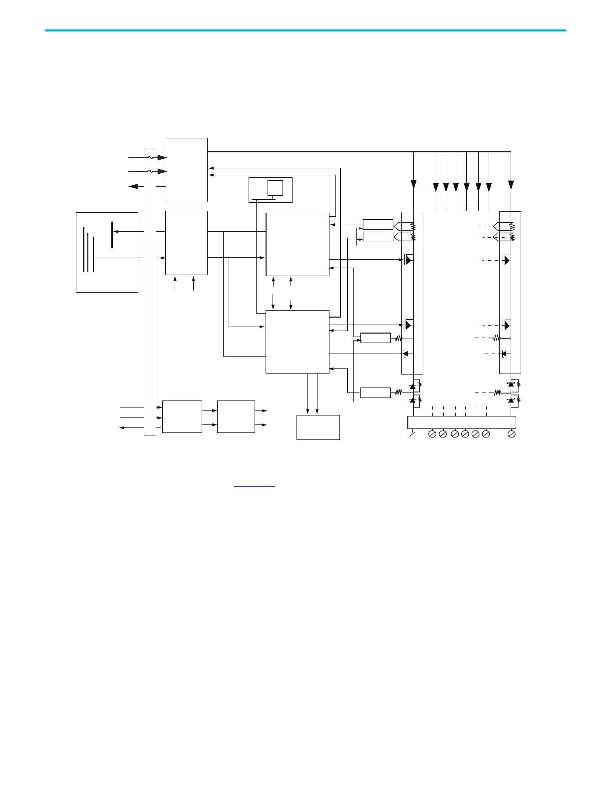
1715-OB8DE Digital Output Module FBD
Figure 38 - 1715-OB8DE Functional Bock Diagram (FBD)
See Figure 38. Two independent output switch control units control the field
output channel. The field output circuitry is galvanically isolated from the
processor input commands and response lines by an isolated interface circuit.
This architecture helps protect the system processors from faults in the output
control circuits of the module and possible field device faults.
The internal isolated power supply produces module power, which the dual
redundant system power inputs supply. Over- and undervoltage protection is
applied to the module internal power supply outputs.
Command packets are received from the processor module via the EtherNet/IP
network. The output switch control units decode and vote the output data that
is addressed to them and set the output FET switches accordingly. The output
voltages are produced from the 24V DC field power input voltages by a power
combiner circuit. Each output channel has a pair of FET switches arranged in a
series that are independently controlled. Load current and voltage monitoring
is provided for each switch. Output channel protection makes sure that the
output circuit is switched off when the channel load current exceeds a safe
limit.
VFIELD 1
VFIELD 2
Response Bus
24V
FIELD
POWER
Response
Command A,B,C
I/0 Command Bus
I/0 Backplane
VFIELD
OV RTN
Power
Combiner
Isolated
Backplane
Interface
PWR
Power
Valid
PWR
Power
Valid
Response
Command
Command
Dual
Redundant
System
Power
SYS_24V1
SYS_24V2
SYS_OV
Isolated
Power
Supply
Over/Under
Voltage
Protection
PWR
Power
Valid
LED Array
Front Panel
Channel
Status
Module
Status
VREF
Termination
Assembly
CH0 CH7
Transient
Suppression
VMON B
VMON A
Output Control
Output Control
Reverse Voltage
Blocking
IMON B
IMON A
VREF
Data Management
& Output Switch
Control A
PWR Feed Combiner Drives
SPI
Flash
Response
Combined Power Feed
Termination
Assembly
Data Management
& Output Switch
Control B
 Loading...


