62 Rockwell Automation Publication 1715-UM001J-EN-P - December 2020
Chapter 2 Installation Instructions
Install the I/O Base Unit You can install up to three I/O modules on an I/O base unit. The I/O base unit
has an incoming I/O base connector on the left-hand side of the unit, an
outgoing I/O base connector on the right-hand side, and, on the front,
connections for three I/O termination assemblies and three I/O modules. The
locations for each I/O termination assembly and I/O module connectors are
paired, and together represent an I/O module slot.
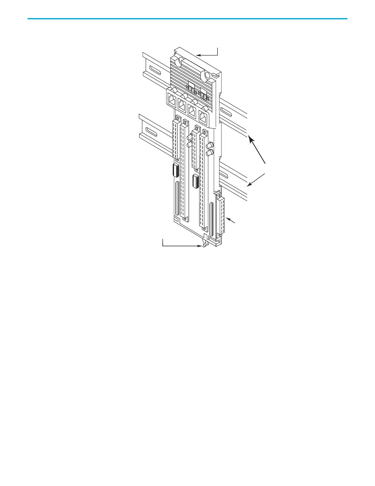
To mount the 1715-A3IO base unit, follow these steps.
1. Mount each 1715-A3IO base unit onto the DIN rails to the right of the 1715-
A2A adapter base unit.
2. Slide the base unit to the left until the joining connectors are fully mated.
Adapter Base Unit
Retaining Lever
DIN Rails
 Loading...


