Rockwell Automation Publication 1715-UM001J-EN-P - December 2020 85
Chapter 2 Installation Instructions
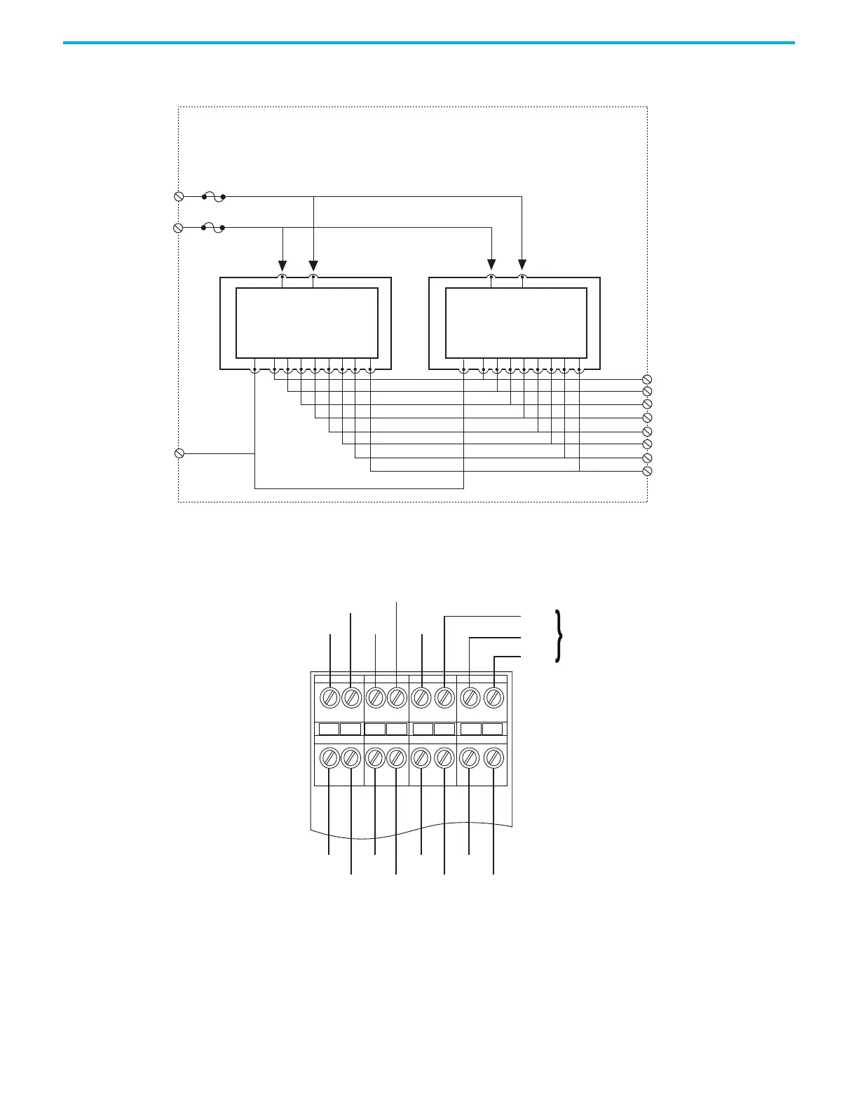
Figure 42 - 1715-TADOB8DE Digital Output Duplex Termination Assembly Connections
Figure 43 - Digital Output Termination Assembly Field Wiring
Digital Output Slew Tolerance
It is possible during sustained periods of abnormal field supply or output
signal condition slewing that channels can be declared faulted as a
consequence of diagnostics that are otherwise designed to verify the channels
are operating within their designed safety accuracy.
VFIELD1
+24V DC
VFIELD2
+24V DC
VFIELD RTN
OV
Fuse F2
Fuse F1
Digital Output
Fail Safe Channel
Array
Connector J1
DO Module
Digital Output
Fail Safe Channel
Array
Connector J2
DO Module
DO CH0
DO CH1
DO CH2
DO CH3
DO CH4
DO CH5
DO CH6
DO CH7
33004 M DO Duplex
Output Connections
OV OV OV
V1
+
+
V2
V1 +
V2 +
OV
To
Next
TA
(if tted)
TB1 TB2 TB3 TB4
CH0 CH2 CH4 CH6
CH1 CH3 CH5 CH7
32105 M DO TA Field Wiring
 Loading...


