Rockwell Automation Publication 1715-UM001J-EN-P - December 2020 87
Chapter 2 Installation Instructions
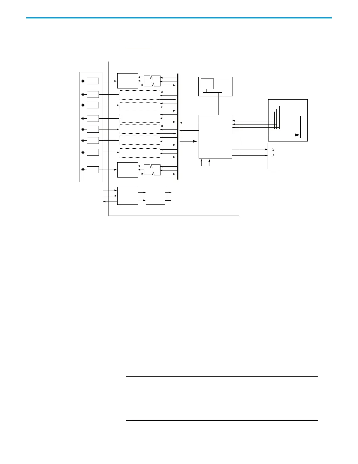
1715-TASIF16 Analog Input Termination Assembly Functional Block Diagram
Figure 45 is the diagram for the analog input termination assembly.
Figure 45 - 1715-Analog Input Termination Assembly Functional Block
Each input signal is routed through the termination assembly to two input
measurement devices. These devices determine the input status and channel
condition and generate the input data for the controller.
Signal and power isolation circuits separate each input channel from the rest
of the system, thus protecting the system components from field faults.
The internal isolated power supply from the 24V DC dual redundant system
power inputs produces module power. The isolated power supply provides
power to the module and is protected by over-voltage and undervoltage
detection circuits. Supply voltage monitoring initiates a warning signal and
Power-off Protection mode when a power failure is detected.
Internal diagnostics, which the adapter controls, test the module at routine
intervals of 50…100 ms. An independent watchdog arrangement also monitors
the module operation and provides more fault containment by activating a
shutdown mechanism when a fault is detected.
Channel 0
Channel 1
Channel 2
Channel 3
Channel 4
Channel 5
Channel 6
Channel 7
Field
Inputs
Termination
Assembly
Dual
Redundant
System
Power
SYS_24V1
SYS_24V2
SYS_OV
Dual Input
Measurement
Device
Isolated
Power
Supply
Over/Under
Voltage
Protection
PWR
Power
Valid
Isolator
PWR
CMD
RES
PWR
CMD
RES
PWR
CMD
RES
PWR
CMD
RES
PWR
CMD
RES
PWR
CMD
RES
PWR
CMD
RES
Dual Input
Measurement
Device
Isolator
PWR
CMD
RES
PWR
CMD
Input Data
Data Management
FPGA
PWR
Power
Valid
SPI
Flash
PMA Commands
PMB Commands
PM Commands
I/O Command Bus
Response Bus
Front Panel
LEDS
I/O Backplane
Input Data
Module Status
Channel Status
32106 M Function Block Diagram
Typical Circuit
IMPORTANT
If a fault occurs during normal operation in a duplex configured
system, a faulted input module can be removed and replaced
without disrupting the input signals to a live system.
Use extreme caution when removing and inserting I/O modules
under power because bending or damaging the pins can fault the
system.
 Loading...


