Rockwell Automation Publication 1715-UM001J-EN-P - December 2020 27
Chapter 1 Redundancy System Overview
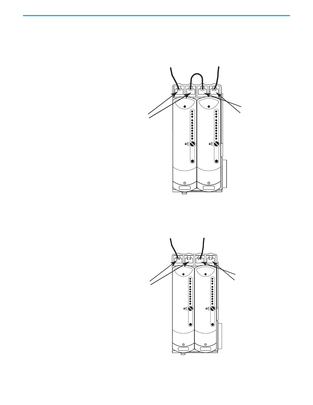
For a DLR (Ring) Topology, the Ethernet ports of the adapters are configured
with the outward-facing ports (Port 1 of Module A and Port 2 of Module B)
operating as a 2-port switch. Port 2 of Module A and Port 1 of Module B are
chained together.
Figure 10 - DLR (Ring) Ethernet Topology
For a STAR Topology, the Ethernet ports of the adapters are configured with
the leftmost ports (Port 1 of Module A and Port 1of Module B) operating as a
2-port switch. The rightmost ports on each adapter are left unused.
Figure 11 - STAR Ethernet Topology
Module Status
Redundancy Status
Network Status
Rack Status
Ethernet 1
Ethernet 2
Reset
Ethernet 1
Ethernet 2
Reset
Module A
Port 1
Port 2
Module B
Port 1
Port 2
Module Status
Redundancy Status
Network Status
Rack Status
Ethernet 1
Ethernet 2
Reset
Ethernet 1
Ethernet 2
Reset
Module A
Port 1
Port 2
Module B
Port 1
Port 2
Module Status
Redundancy Status
Network Status
Rack Status
Module Status
Redundancy Status
Network Status
Rack Status
 Loading...


