5–9Part Replacement Procedures
Publication 1336 IMPACT-6.8 – November, 2002
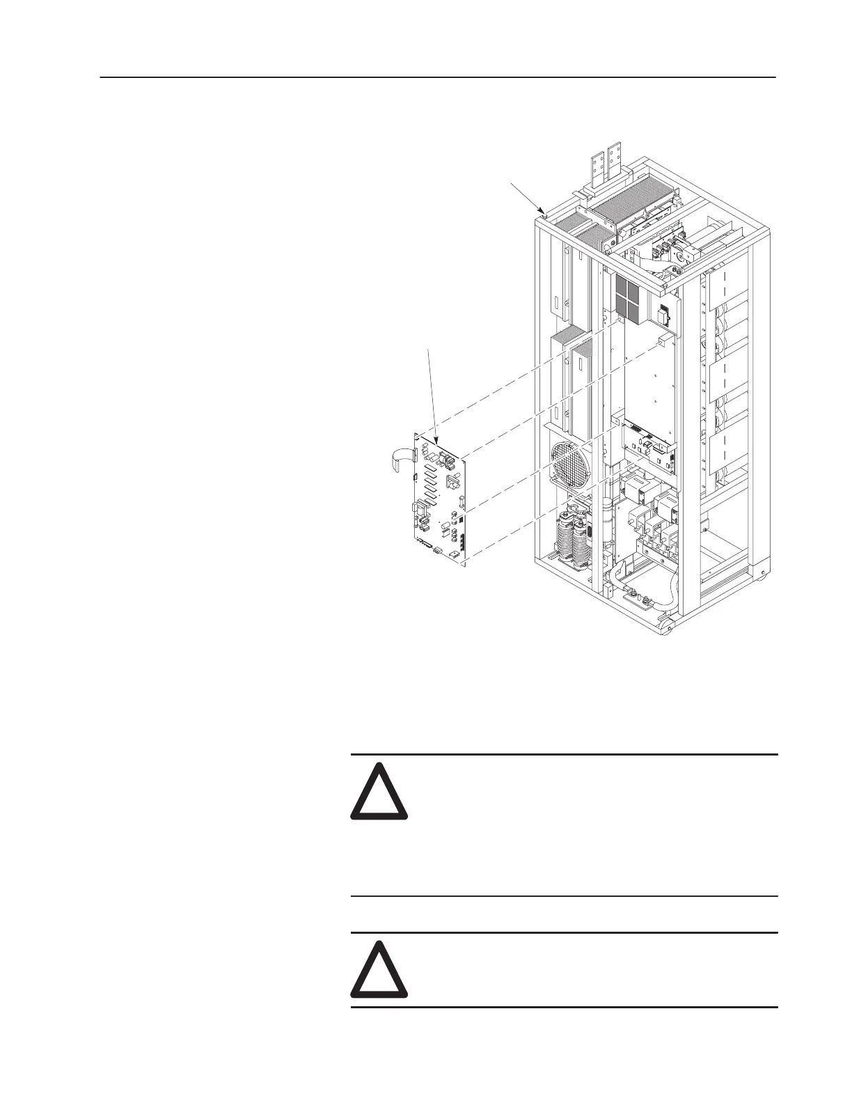
Figure 5.5
Gate Driver Board
Gate Driver
Board
Inverter Bay w/o Cabinet
(Control Board Mounting
Plate Removed)
Installation
Install the Gate Driver Board in reverse order of removal. Refer to
Table 3.A – Fastener Torque Specifications.
!
ATTENTION: When installing the wire harness
connecting Gate Driver Board connector J9 to
Common Bus Precharge Board connector J3, align the
wires on the harness terminals with the pins on the
board connectors. Incorrect harness connection may
result in faulty drive operation and may damage the
equipment.
!
ATTENTION: Replace all guards before applying
power to the drive. Failure to replace guards may result in
death or serious injury.
 Loading...


