4–11Component Test Procedures
Publication 1336 IMPACT-6.8 – November, 2002
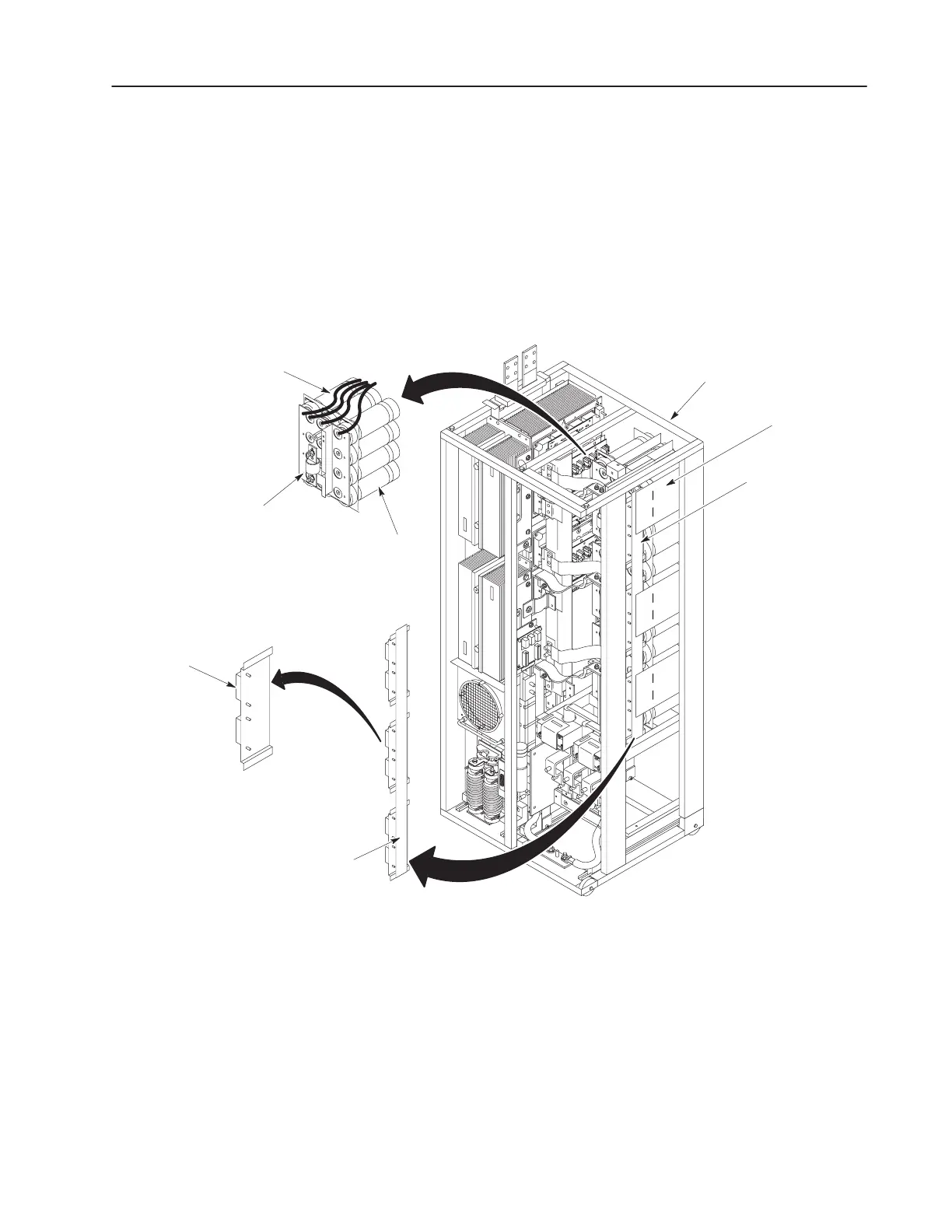
2. Connect a meter lead to the leads from each end of a Volt-Sharing
Resistor. Refer to Figure 4.6. Expect a meter reading of 4.3k
Ohms +/– 10%.
3. Repeat the above test for each Volt-Sharing Resistor.
4. If any resistors are out of tolerance, refer to Removing
Volt-Sharing Resistors and Dual Diodes in Chapter 5, Part
Replacement Procedures.
Figure 4.6
Balancer Plate Assembly
Inverter Bay w/o Cabinet
Balancer Plate
Assembly
Capacitor Bank
Assembly
Volt-Sharing
Resistor and
Dual Diode
Leads
Volt-Sharing
Resistor
Balancer Plate
Assembly
Bus Capacitors
Fuse
Dual Diode Test
1. Set your meter to test diodes.
2. Test D1 and D2. Table 4.E shows meter connections, and nominal
meter readings for those connections. Refer to Figure 4.4 for
component locations.
 Loading...


