5–11Part Replacement Procedures
Publication 1336 IMPACT-6.8 – November, 2002
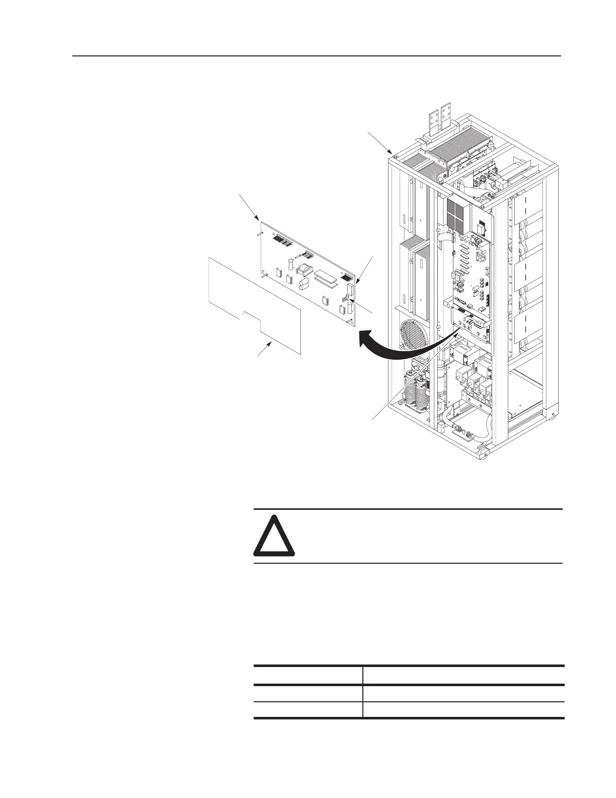
Figure 5.6
Common Bus Precharge Board
Common Bus
Precharge Board
High Voltage
Guard
Inverter Bay w/o Cabinet
(Control Board Mounting Not
Shown for Clarity)
Precharge Board
Mounting Frame
TB1
W1
Installation
!
ATTENTION: The wrong jumper setting at W1 will
either damage the Common Bus Precharge Board, or
prevent proper precharge operation.
1. The leads attached to TB1 are either at 24VDC or 120VAC. Set
the jumper position on W1 for the correct TB1 voltage. Refer to
Table 4.G.
Table 5.A
W1 Jumper Settings
olta e etween ea s Attache at T
W1
i
i
V
g
B
L
d
d
B1
1 to 2 24VDC
2 to 3 120VAC
 Loading...


