5–2 Part Replacement Procedures
Publication 1336 IMPACT-6.8 – November, 2002
• Wear a wrist-type grounding strap that is grounded to the chassis.
• Attach the wrist strap before removing the new circuit board from
the conductive packet.
• Remove boards from the drive and immediately insert them into
their conductive packets.
For a list of tools required, tightening sequences, and fastener torque
specifications, refer to Fastener Torque Specifications in Chapter 3,
Access Procedures.
Allen-Bradley Adjustable Frequency AC Drives are modular by
design to enhance troubleshooting and spare parts replacement,
thereby helping reduce production down-time.
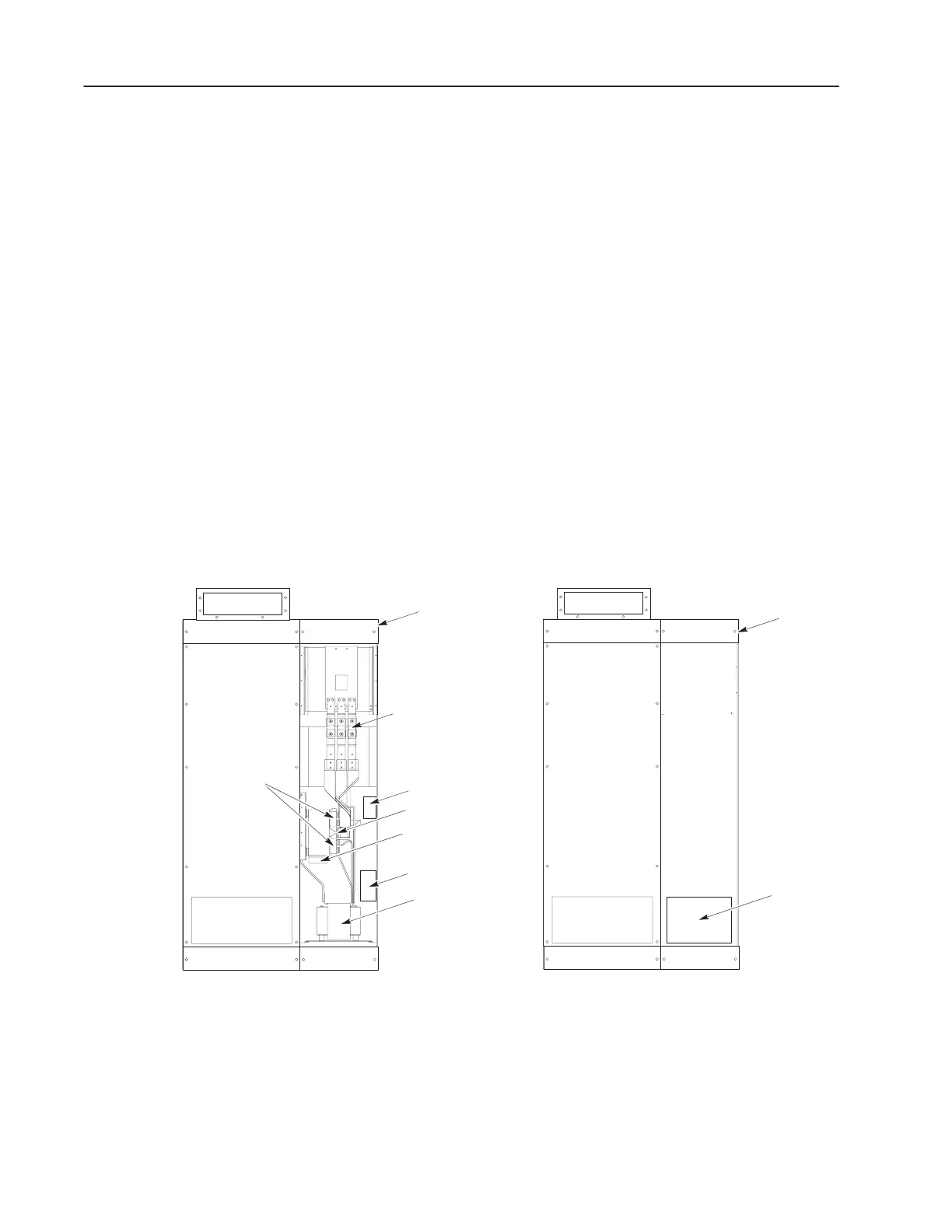
Figure 5.2 and 5.1 identify the main components of a typical drive.
Component designs vary slightly among the different drive ratings.
Also, the Converter Bay is configured to each order and can vary
considerably. For that reason, Converter Bay illustrations show less
detail than the Inverter Bay illustrations.
Figure 5.1
Converter Bay Parts (Typical)
Fuses
F1, ..., F3A
MOV (back) and
Line Loss Relay
Fan
Converter
Bridge Diodes
Thermal Switch
Converter Fans
DC Snubber Board
DC Bus Inductor
Converter
Bay
Converter
Bay
Detailed Product
Identification
 Loading...


