5–21Part Replacement Procedures
Publication 1336 IMPACT-6.8 – November, 2002
6. Remove the screws fastening the Power Module Gate Interface
Board to the Power Modules.
7. Remove the Power Module Gate Interface Boards.
8. Follow the torque sequence, as illustrated in Chapter 3, Access
Procedures, Figure 3.3, and remove the screws fastening the
Power Module to the heat sink.
9. Remove and discard the Preform, if present.
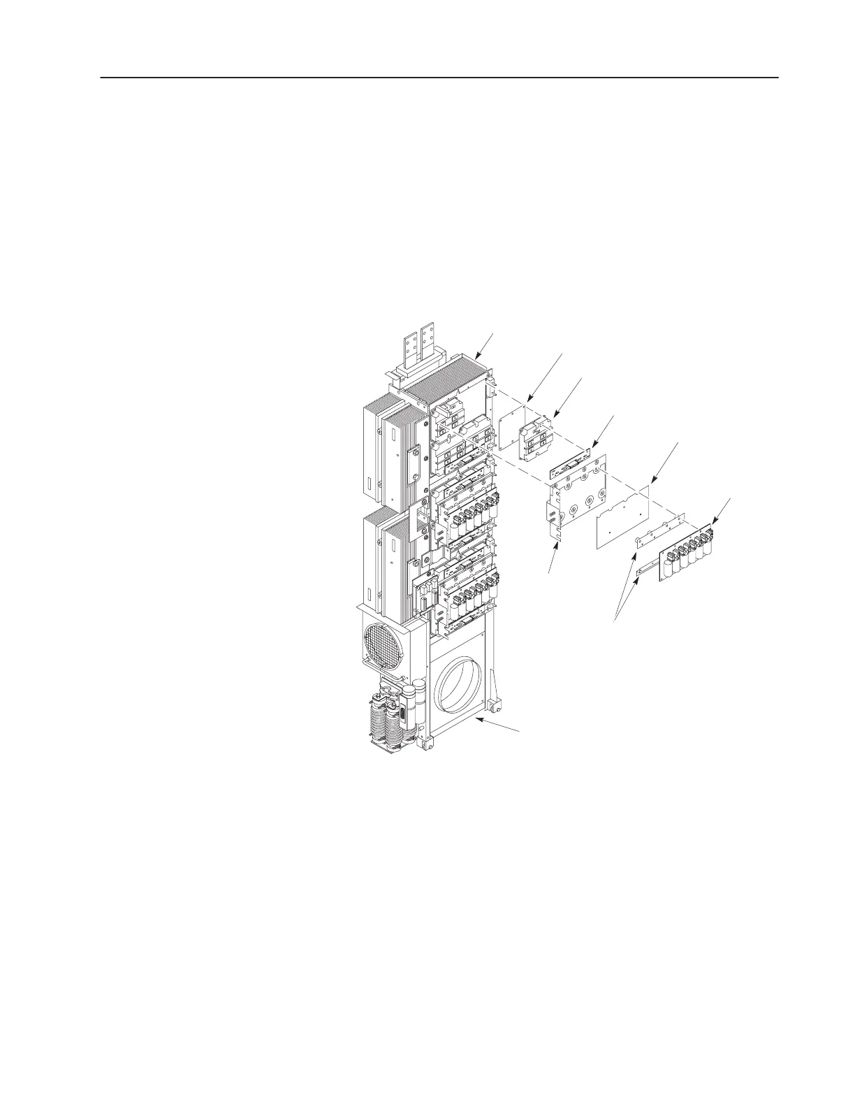
Figure 5.11
Power Modules
Power Module
Snubber Bus
Bar (+ and –)
Power Module Gate
Interface Board
Power Module
Snubber Board
Power Module
Bus Bar
Preform
(only on drives dated before about 2001)
Insulator
Inverter Assembly w/o Cabinet
Main Heat Sink
AB1096
Installation
1. Clean all surfaces between the Power Module and the Main Heat
Sink using a soft, clean cloth.
2. Apply layer of thermal grease (supplied) between Power Module
and the Main Heat Sink. Discard old Preform, if present.
3. Install the Power Module in reverse order of removal. Refer to
Fastener Torque Specifications in Chapter 3, Access Procedures.
 Loading...


