5–43Part Replacement Procedures
Publication 1336 IMPACT-6.8 – November, 2002
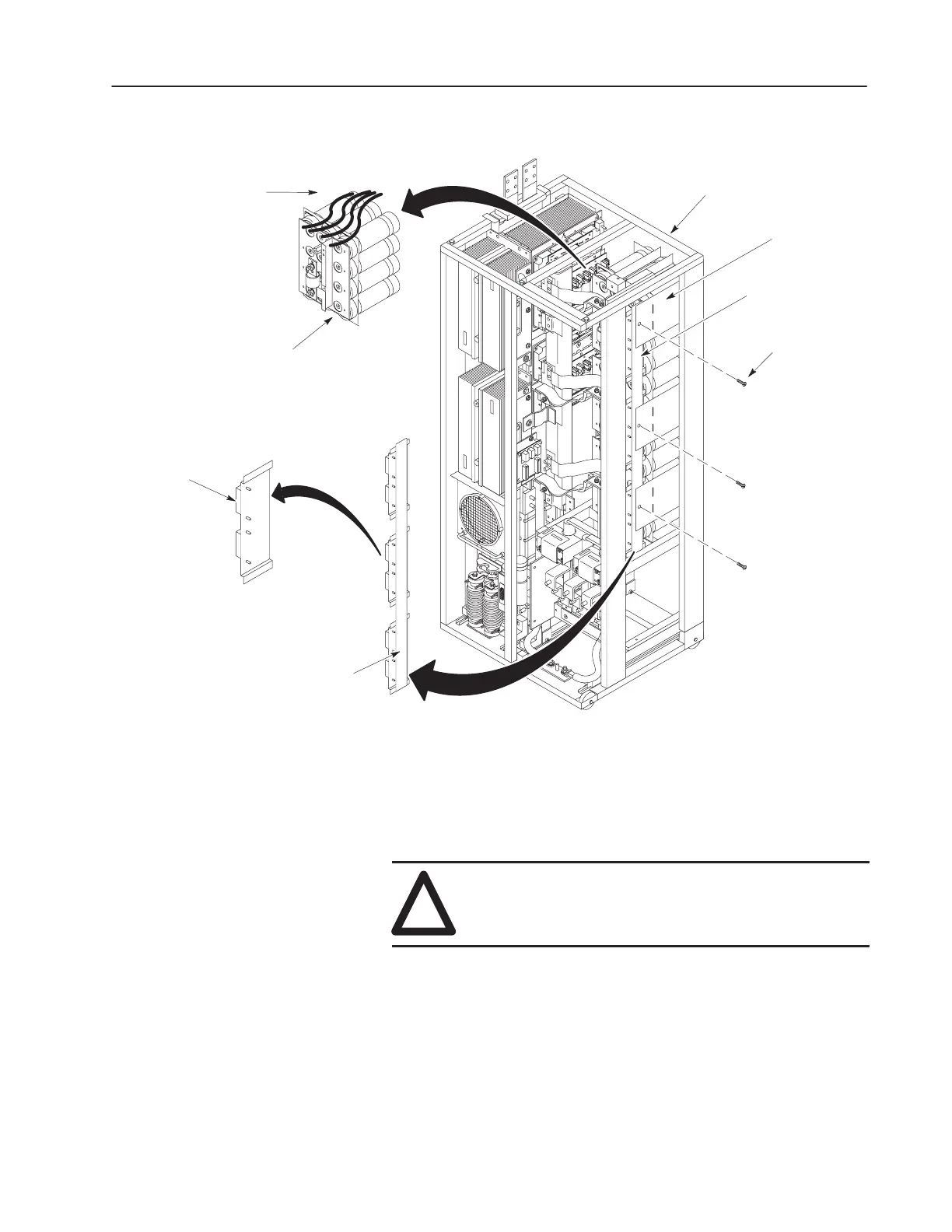
Figure 5.24
Balancer Plate Assembly
Inverter Bay w/o Cabinet
Balancer Plate
Assembly
Screws
(3)
Capacitor Bank
Assembly
Volt-Sharing
Resistor and
Dual Diode
Leads
Volt-Sharing
Resistor
Balancer Plate
Assembly
Bus Capacitors
Installation
1. Install the capacitor assembly in reverse order of removal. Refer
to Fastener Torque Specifications in Chapter 3, Access
Procedures.
!
ATTENTION: Replace all guards before applying
power to the drive. Failure to replace guards may result
in death or serious injury.
 Loading...


