4–7Component Test Procedures
Publication 1336 IMPACT-6.8 – November, 2002
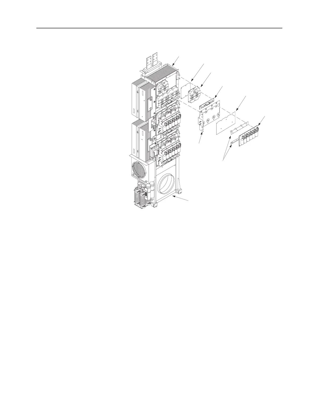
Figure 4.2
Power Modules
Power Module
Snubber Bus
Bar (+ and –)
Power Module Gate
Interface Board
Power Module
Snubber Board
Power Module
Bus Bar
Preform
(only on drives dated before about 2001)
Insulator
Inverter Assembly w/o Cabinet
Main Heat Sink
AB1096
Transistor Test
1. Remove the screws fastening the positive and negative Snubber
Bus Bars to the Power Module Bus Bar.
2. Remove the screws fastening the Power Module Bus Bar to the
Power Modules.
3. Carefully remove the bus bar. Do not damage the Insulator.
4. Set your meter to test diodes.
5. Test the Power Modules. Table 4.C shows meter connections and
ideal meter readings for those connections. Refer to Figure 4.3 for
meter connection locations.
6. Replace a Power Module if meter readings are not as shown.
Refer to Replacing a Power Module in Chapter 5, Part
Replacement Procedures.
 Loading...


