5–27Part Replacement Procedures
Publication 1336 IMPACT-6.8 – November, 2002
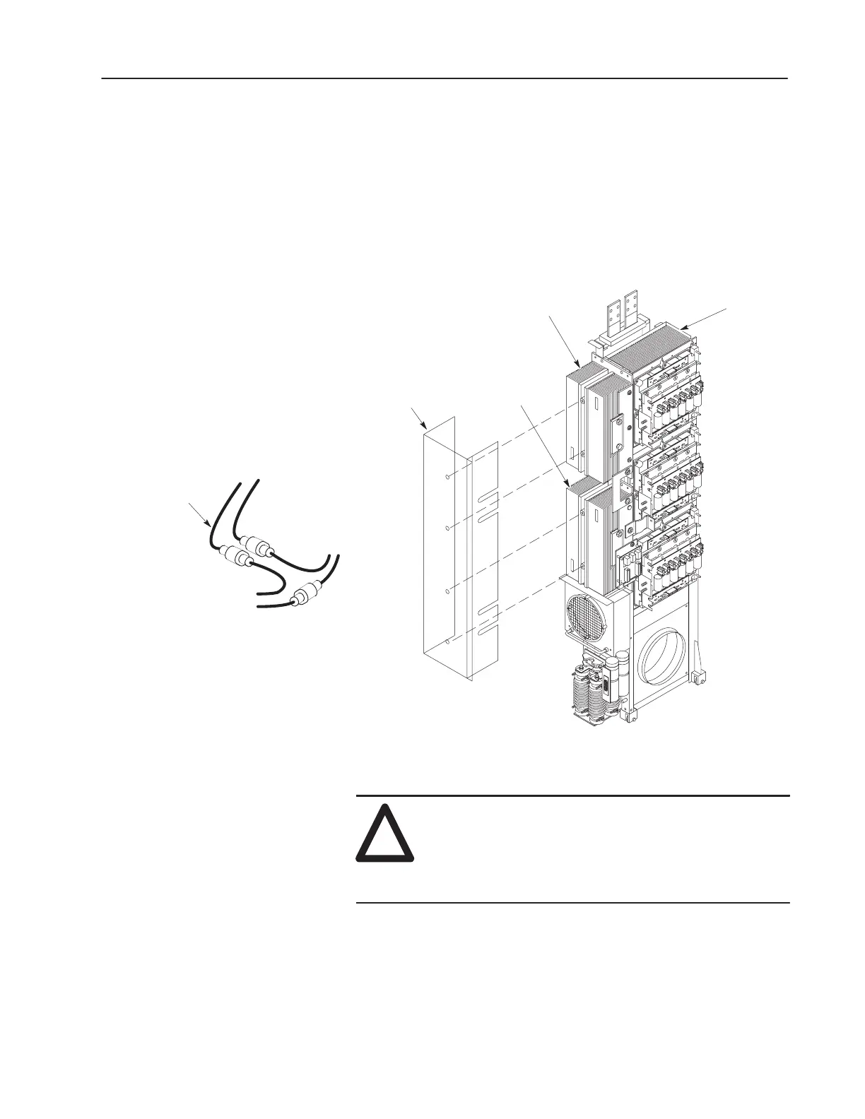
Replacing a Diode, SCR or Thermostat
The Diode and SCR Heat Sink Assemblies are mounted on the front
of the Inverter Assembly. The SCR Heat Sink Assembly also
contains the Thermostat. Access to these components does not
require removal of the Inverter Assembly from the Inverter Bay.
Figure 3.17 shows the Inverter Assembly removed for clarity.
Figure 5.14
Diode and SCR
Inverter
Assembly
SCR Heat Sink
Diode Heat Sink
HV Guard
To Control
Board J1
To Thermostat
(Through HV Guard)
To Thermistor
(Power Module
Heat Sink)
Harness
Removal
!
ATTENTION: Wear a wrist-type grounding strap
when servicing 1336 IMPACT drives. Failure to
protect drive components against ESD may damage
drive components. Refer to Electrostatic Discharge
Precautions at the beginning of this chapter.
1. Remove power and check for zero voltage in the drive. Refer to
Opening the Drive Enclosure in Chapter 3. Access Procedures.
2. A harness joins the Thermistor (Power Module) and Thermostat
(SCR) to the Control Board (Figure 3.17). Disconnect the
Thermostat leads from this harness.
 Loading...


