3–28 Access Procedures
Publication 1336 IMPACT-6.8 – November, 2002
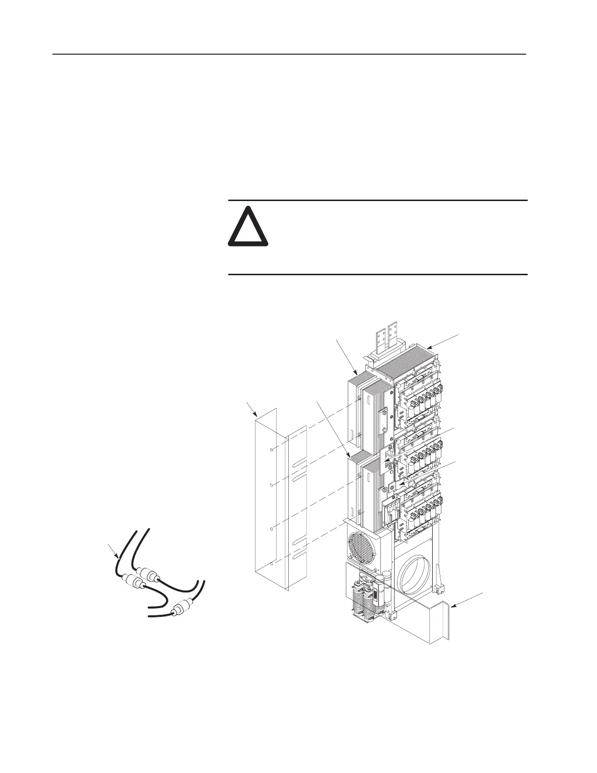
Removing Diode and SCR Heat Sinks
You may need to remove the Diode or SCR Heat Sink Assemblies if
you have trouble replacing a Diode, SCR or Thermostat. Access to
these components does not require the removal of the Inverter
Assembly from the Inverter Bay. Figure 3.17 shows the Inverter
Assembly removed for clarity.
Removal
!
ATTENTION: Wear a wrist-type grounding strap
when servicing 1336 IMPACT drives. Failure to
protect drive components against ESD may damage
drive components. Refer to Electrostatic Discharge
Precautions at the beginning of this chapter.
Figure 3.17
Diode and SCR
Inverter Assembly
SCR Heat Sink
Diode Heat Sink
U-Shaped Bus Bar
Precharge to Spine
Flex Bus
SCR HV
Guard
Lower HV
Guard
To Control
Board J1
To Thermostat
(Through HV Guard)
To Thermistor
(Power Module
Heat Sink)
Harness
1. Perform the following procedures found earlier in this chapter:
• Opening the Drive Enclosure
• Removing the Control Board Mounting Plate
 Loading...


