6–2 Replacement Parts List
Publication 1336 IMPACT-6.8 – November, 2002
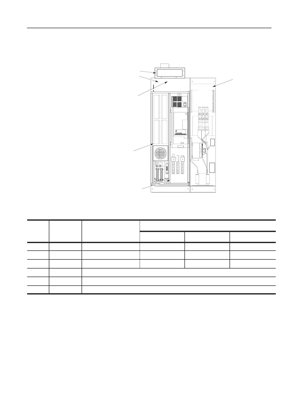
Figure 6.1
Replacement Parts
1
2
3
4
5
6
Table 6.A
Replacement Parts
Symbol on
Procedures
R
d
Schematics
D
i
i
Access
1
Test Replacement
1 Fan1
2
Main Enclosure Fan Does Not Apply (DNA) DNA DNA
2 OL12 Overload Relay DNA DNA DNA
3 F20 – F22 Fuse DNA DNA DNA
4 – Inverter Assembly – Refer to Table 6.B and Table 6.C
5 – Capacitor Assembly – Refer to Table 6.D
6 – Converter Bay
2
– Refer to Table 6.E
1. Access always requires the procedure: Opening the Drive Enclosure.
2. The schematics supplied for configured systems include the spare parts list for the Converter Bay
and the enclosure fan.
Replacement Parts Listing
 Loading...


