6–3Replacement Parts List
Publication 1336 IMPACT-6.8 – November, 2002
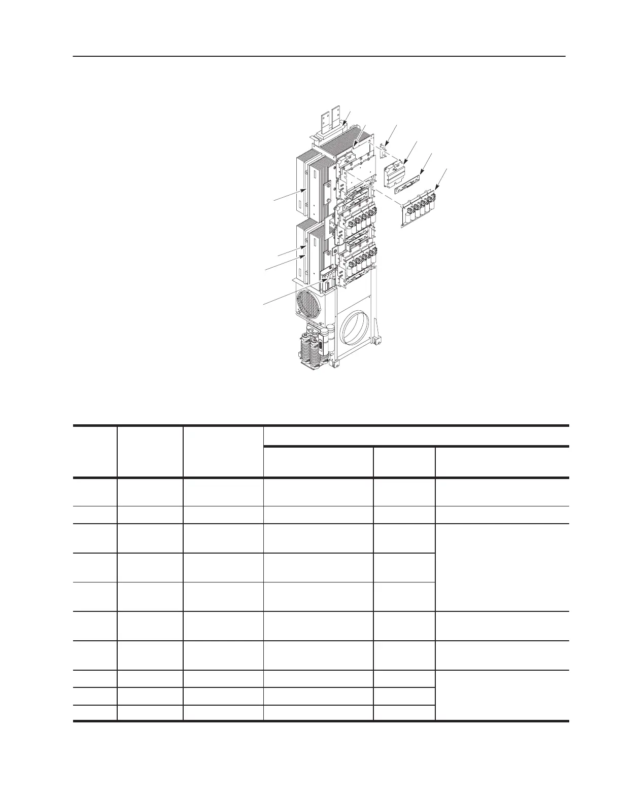
Figure 6.2
Inverter Assembly Replacement Parts
6
15
17
16
20
19
18
14
13
12
11
Table 6.B
Inverter Assembly Replacement Parts
Symbol on
Procedures
Callout
Chapter 7
Schematics
Description
Access
1
(Ref: Ch. 3)
Test
(Ref: Ch. 4)
Replacement
(Ref: Ch. 5)
11 CT3 Current Fault
Transformer
DNA DNA Replacing the Current Sense
Transformer
12 NTC1 Thermistor DNA Test 5 Replacing a Thermistor
13 R20 – R25 Power Module
Snubber Resistor
Pulling the Inverter Assembly Test 2
Replacing a
ower
odule
14 Q11 – Q12, . . .
Q61 – Q62
Power Module
Transistor
Pulling the Inverter Assembly Test 2
15 A23 – A28 Power Module Gate
IF Board
Pulling the Inverter Assembly DNA
16 A20 – A22 Power Module
Snubber Board
Pulling the Inverter Assembly Test 2 Replacing a Power Module Snubber
Board
17 – Input Rectifier
Snubber Board
DNA DNA Replacing an Input Rectifier Board
18 SCR1 SCR DNA Test 4
Replacing a Diode, S
R, or
19 THS1 Thermostat DNA Test 5
hermostat
20 D4 Diode DNA Test 4
1. Access always requires the procedure: Opening the Drive Enclosure.
 Loading...


