5–33Part Replacement Procedures
Publication 1336 IMPACT-6.8 – November, 2002
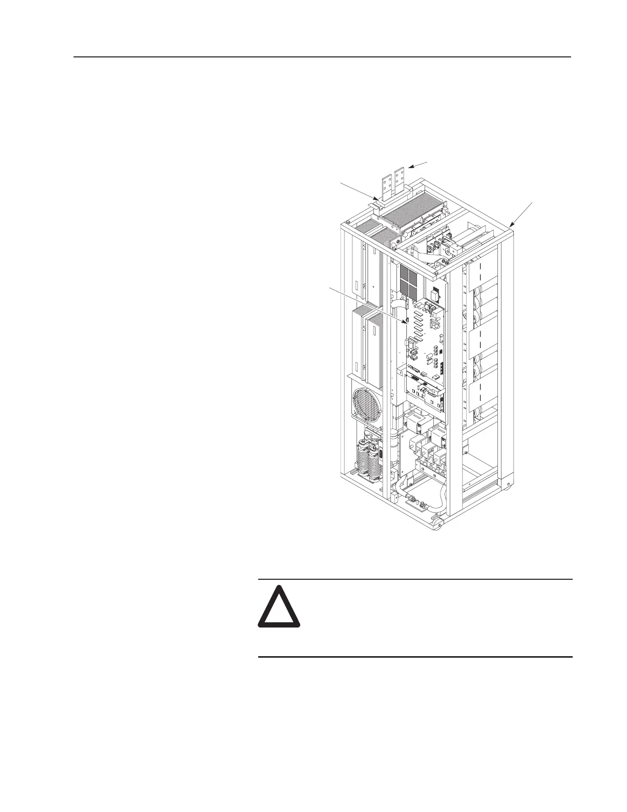
Replacing the Ground Fault CT
The Ground Fault CT is located at the top of the Inverter Assembly.
Figure 5.18
Ground Fault CT
Gate Driver Board
Inverter Bay w/o Cabinet
(Control Board Not
Shown for Clarity)
Ground Fault CT
DC Input Lines
Removal
!
ATTENTION: Wear a wrist-type grounding strap
when servicing 1336 IMPACT drives. Failure to
protect drive components against ESD may damage
drive components. Refer to Electrostatic Discharge
Precautions at the beginning of this chapter.
1. Remove power and check for zero voltage in the drive. Refer to
Opening the Drive Enclosure in Chapter 3, Access Procedures.
 Loading...


