5–32 Part Replacement Procedures
Publication 1336 IMPACT-6.8 – November, 2002
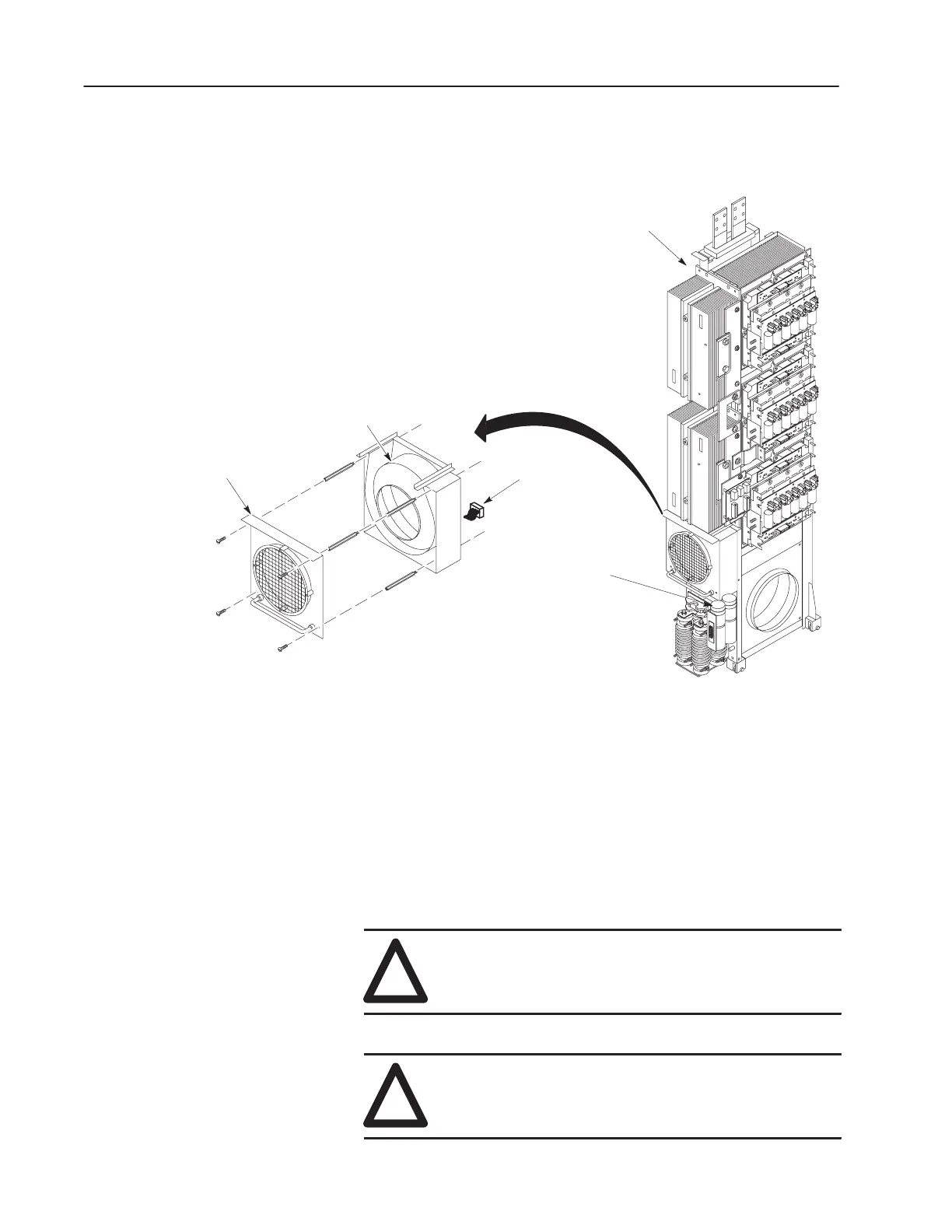
Refer to Figure 5.17, and the following steps to remove Fan 2.
Figure 5.17
Fan 2 Assembly
Fan 2
Fan 2 Cover
Inverter Assembly
w/o Cabinet
Fan 2
Wiring
Harness
Capacitors
1. Remove the screws fastening the Fan 2 Cover to Fan 2.
2. Remove the standoffs that fasten Fan 2 to the Inverter Assembly.
3. Disconnect the Fan 2 wiring harness.
4. Remove fan from assembly.
Installation
Install Fan 1 and Fan 2 in reverse order of removal.
!
ATTENTION: Take care to avoid pinching any wires
as the fan assemblies are mounted. Also, keep wiring
clear of the the Resistors in the Resistor Assembly.
!
ATTENTION: Replace all guards before applying
power to the drive. Failure to replace guards may result
in death or serious injury.
 Loading...


