5–31Part Replacement Procedures
Publication 1336 IMPACT-6.8 – November, 2002
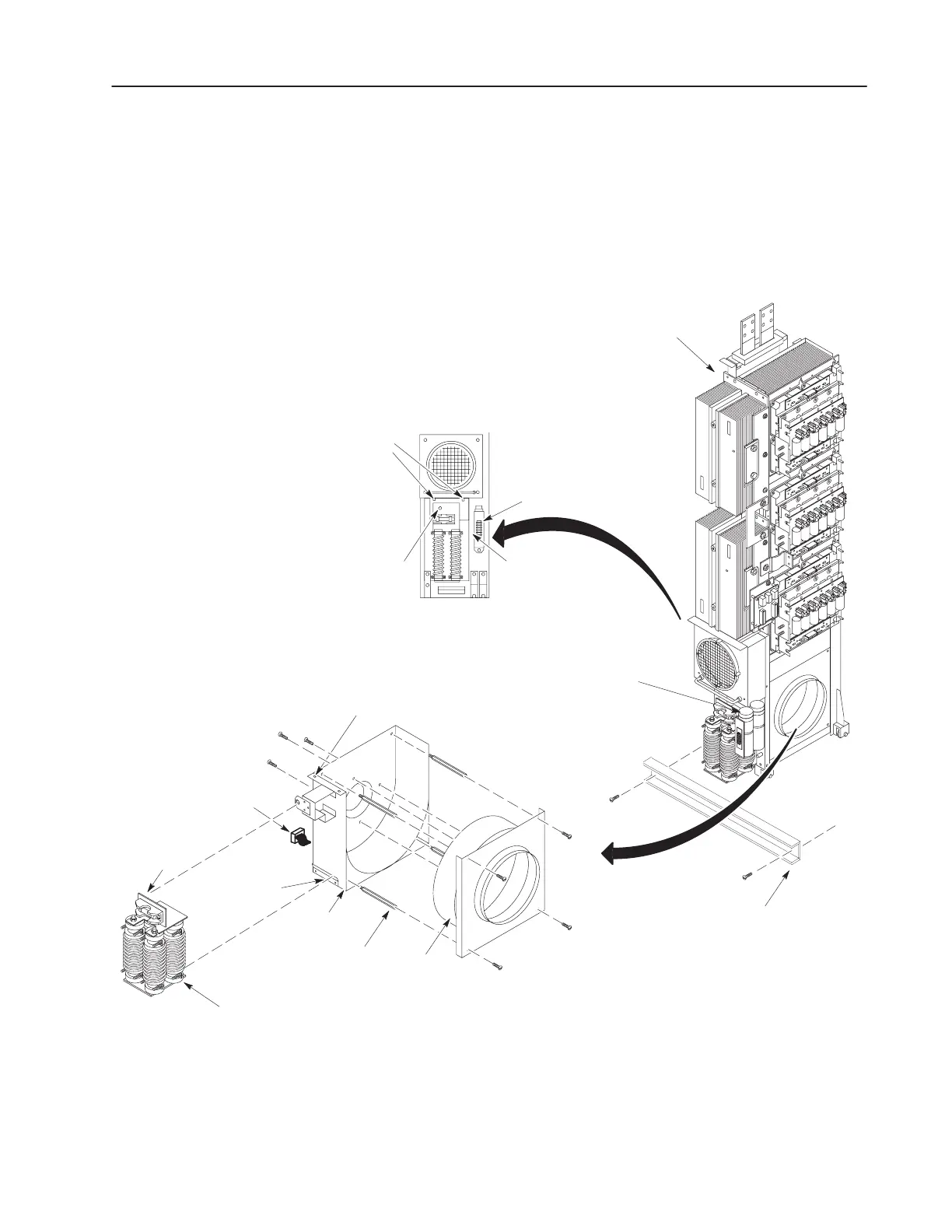
7. Pull Fan 1 toward you to remove it. (You may have to also
disconnect the connectors for the capacitors in order to get
enough clearance to remove the fan.)
8. Remove four bolts on the fan front cover to remove the fan cover.
9. Remove four bolts on the back cover to release the fan.
Figure 5.16
Fan 1 Assembly
AB0610A
Fan 1
Fan 1
Cover
Inverter Assembly
w/o Cabinet
Fan 1
Connector
Standoffs
Spring
Pins (2)
Fan Cover
Screws (4)
Fan
Mounting
Screws (4)
Thumb
Latch
Resistor
Assembly
Lip
Cabinet
Bottom
Bracket
Cabinet
Bottom
Bracket
Capacitors
Spring
Pins (2)
Thumb
Latch
TB1
Connectors
(Not Shown)
 Loading...


