4–10 Component Test Procedures
Publication 1336 IMPACT-6.8 – November, 2002
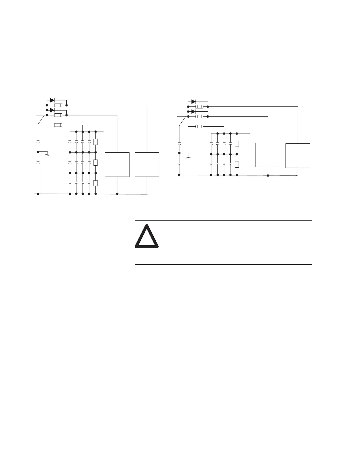
The Volt-Sharing Resistors and Dual Diodes are mounted on the
Balancer Plate Assembly on the right wall of the Capacitor Bank
Assembly. The wiring of this assembly is illustrated in Figure 4.5.
Figure 4.5
Volt-Sharing Resistor Connections to Bus Capacitors
AB0625A
R4 – R6
C13 – C24
C25 – C36
R7 – R9
C5
C9
–
CAP DETAIL
575V
R3
C10 C11 C12
C6 C7 C8
R2
C1 C2 C3 C4
R1
+
F3
D2
F2
F1
D1
C41
C40
X
C1 C2 C3 C4
C8C7C6C5
R1
R2
CAP DETAIL
480V
C9 – C16
R3 – R4
C17 – C24
R5 – R6
D1
D2
F2
F1
F3
+
–
C40
C41
X
–
–
!
ATTENTION: Wear a wrist-type grounding strap
when servicing 1336 IMPACT drives. Failure to
protect drive components against ESD may damage
drive components. Refer to Electrostatic Discharge
Precautions in Chapter 3, Access Procedures.
1. Referring to Opening the Drive Enclosure in Chapter 3, Access
Procedures, remove power and check for zero voltage in the
drive.
Important: Before you remove connections and wires from the
drive components, mark the connections and wires to
correspond with their component connections and
terminals to prevent incorrect wiring during assembly.
2. Remove the black leads on the top row of capacitors in each set
of capacitors.
3. Remove Fuses: F1, F2, and F3.
Volt-Sharing Resistor Test
1. Set your meter to test resistance (range 20k Ohm).
Test 3 – Testing the
Volt-Sharing Resistors and
Dual Diodes
 Loading...


