4–9Component Test Procedures
Publication 1336 IMPACT-6.8 – November, 2002
!
ATTENTION: Replace all guards before applying
power to the drive. Failure to replace guards may result
in death or serious injury.
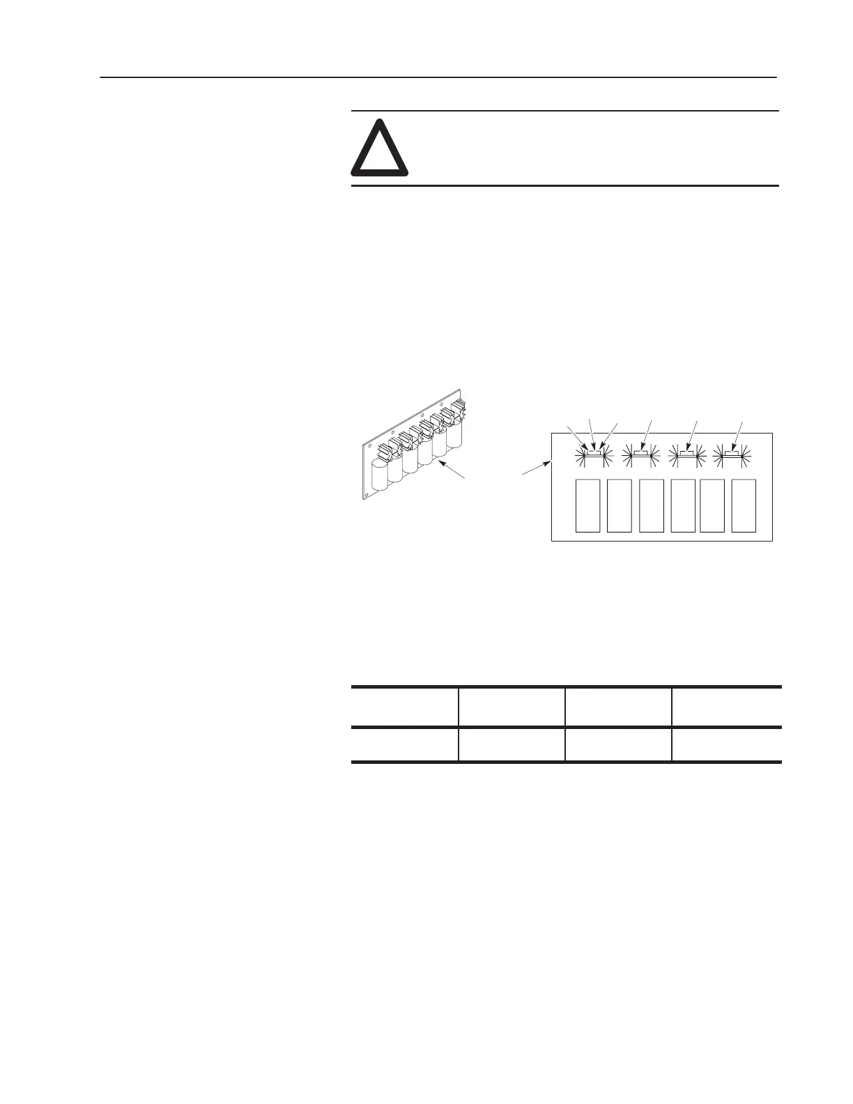
Snubber Board Test
1. Set your meter to test diodes.
2. Test D1 to D4. Table 4.D shows meter connections, and nominal
meter readings for those connections. Refer to Figure 4.4 for
component locations.
Figure 4.4
Power Module Snubber Board
Power Module
Snubber Board
D3
D2
D4
D1
+
–
3. Replace the Snubber Board if your readings do not match the
table readings. Refer to Replacing the Power Module Snubber
Board in Chapter 5, Part Replacement Procedures.
Table 4.D
Power Module Snubber Board Test
Component
Meter (+)
Lead
Meter (–)
Lead
Nominal Meter
Reading*
D1 – D4
Left
Right
Right
Left
Less than 1
Open
Note: Typical malfunction is shorted in both directions.
* Meter Used: Fluke
Model 87, set to “Diode” range.
 Loading...


