4–8 Component Test Procedures
Publication 1336 IMPACT-6.8 – November, 2002
Table 4.C
Power Module Transistor Readings
Meter (+) Lead
Meter (–) Lead Nominal Meter Reading
E C 0.218–0.418
E G Infinite
C E Infinite
C G Infinite
G E Infinite
G C Infinite
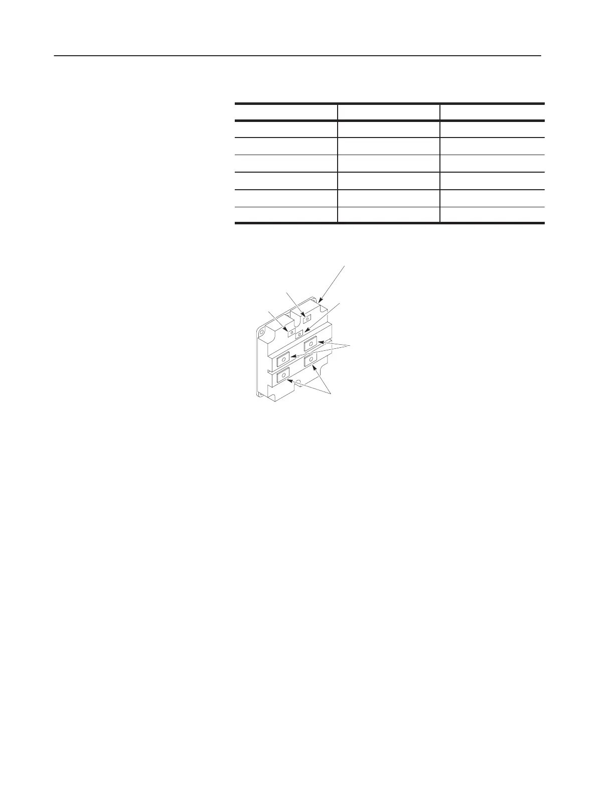
Figure 4.3
Power Module Transistor Test
Gate (G)
Collector (C)
Emitter (E)
Emitter
Power
Tabs (E)
Collector Power
Tabs (C)
Power Module
7. For any Power Module that has failed, continue with the
following tests for the Snubber Resistor and Snubber Board
associated with the failed Power Module.
8. If any Power Module has failed, perform the following:
• Replace the Gate Driver Board, or at least perform Test 1 –
Testing the Gate Driver Board.
• Replace the Power Module Snubber Board.
Snubber Resister Test
1. Set your meter to measure resistance.
2. Test the Power Module Snubber Resistors. The reading should be
16 ohms each.
Two 16-ohm resistors are wired in parallel, in pairs. If measured with
the wiring in place, the effective resistance is 8 ohms total.
3. If open, replace the snubber resistor. Refer to Replacing a Power
Module Snubber Resistor in Chapter 5, Part Replacement
Procedures.
 Loading...


