3–3Access Procedures
Publication 1336 IMPACT-6.8 – November, 2002
Torque Sequence
When mounting components to a drive’s heat sink, component-fastener
torque sequences and tolerances are crucial to component-to-heat sink
heat dissipation.
!
ATTENTION: Component can be damaged if
temporary tightening procedure is not performed to
specification.
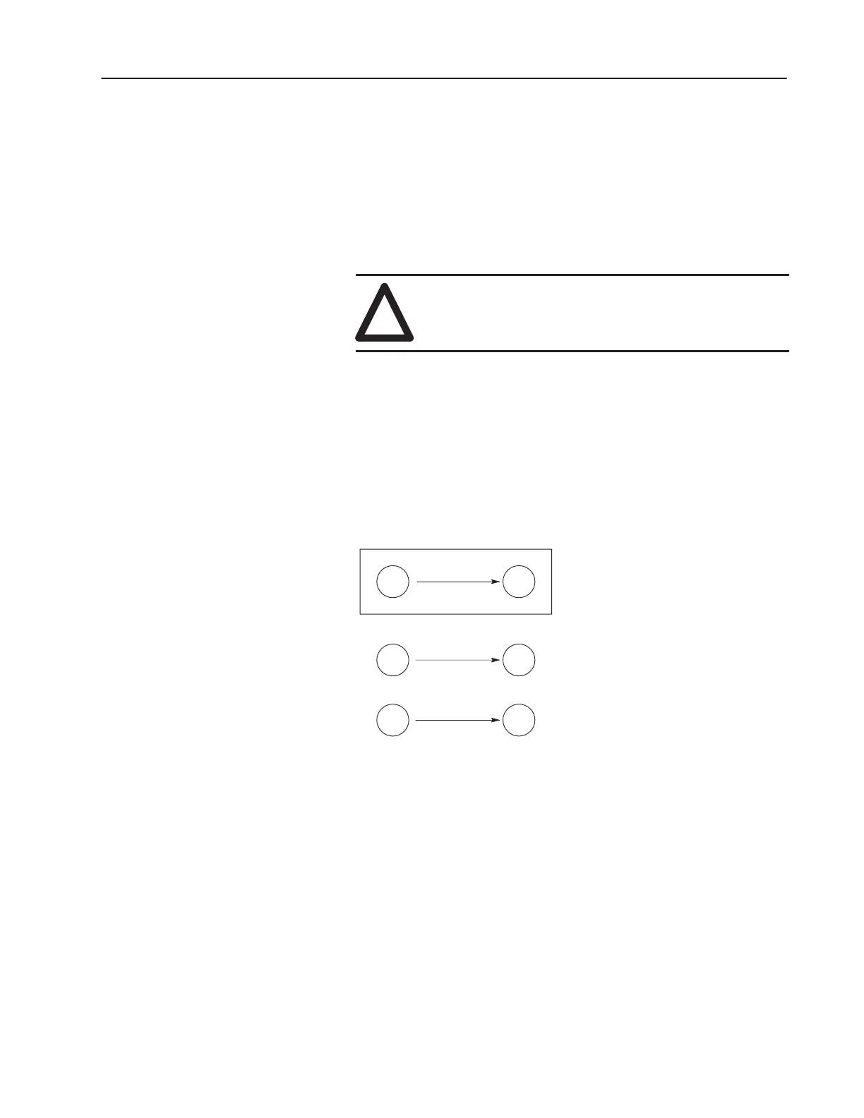
The following illustrates temporary and final tightening sequences
for components fastened to a heat sink using two, four, and six
screws. Temporary torque is 1/3 (33%) of final torque, except
six-point mountings, which require 0.5 N-m (4 in.-lb). The numeric
illustration labels are for your assistance. Drive components do not
carry these labels.
Figure 3.1
Two-Point Mounting
12
12
Two-Point Mounting
Temporary Tighten
Final Tighten
12
Fastener Torque
Specifications
 Loading...


