3–4 Access Procedures
Publication 1336 IMPACT-6.8 – November, 2002
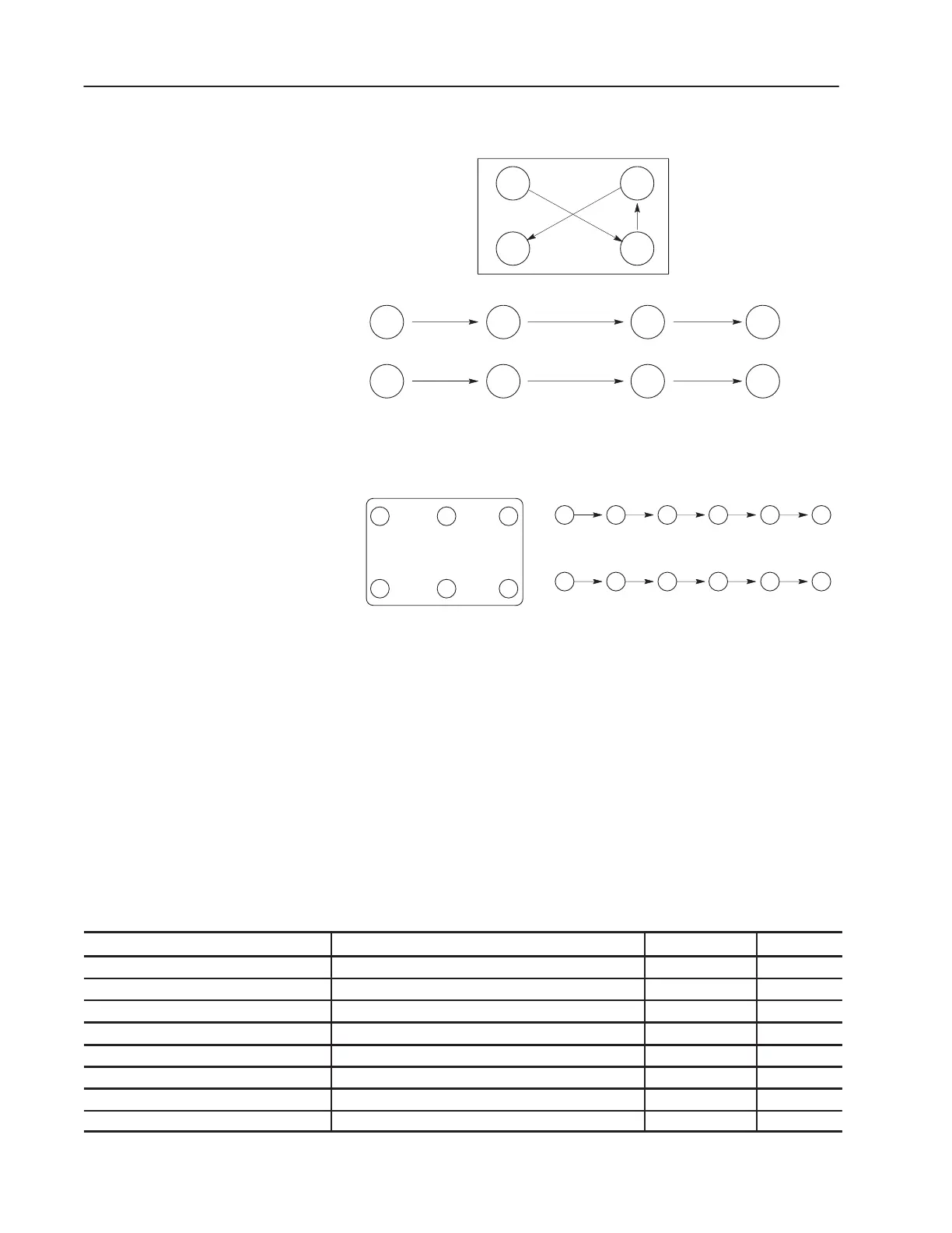
Figure 3.2
Four-Point Mounting
1
4
3
2
12 34
Four-Point Mounting
Temporary Tighten
Final Tighten
12 34
Figure 3.3
Six-Point Mounting
AB0996A
Six-Point Mounting
Temporary Tighten to 0.5 N-m (4 in.-lb)
Final Tighten to 3 N-m (26 in.-lb)
654
123
2 5 3 6 1 4
2 5 3 6 1 4
Do not exceed 0.4 N-m (3 in.-lb) on initial torque or 3.8 N-m (32
in.-lb) final torque of all six screws.
Torque Specifications
The following table lists fastener locations by component, how the
fasteners are used, and torque specifications. Refer to Torque
Sequence in this chapter for fastening two-point, four-point and
six-point components to the heat sink.
Table 3.A
Fastener Torque Specifications
Component
Fastener Application Torque in.-lb Torque N-m
Fan Motor Motor to Fan Cover Assembly 14 1.6
Snubber Resistor Resistor to heat sink 26 2.9
Snubber Bracket Bracket to Power Module Laminated Bus 90 10
Snubber Board Board to Brackets 18 2.0
Snubber Board Board to Input Rectifier Bracket 18 2.0
Volt-Sharing Resistor Resistor to heat sink 26 2.9
Volt-Sharing Resistor Wires to Capacitor Bus Bar Assembly 50 5.6
Thermistor Thermistor to heat sink 14 1.6
 Loading...


