6–5Replacement Parts List
Publication 1336 IMPACT-6.8 – November, 2002
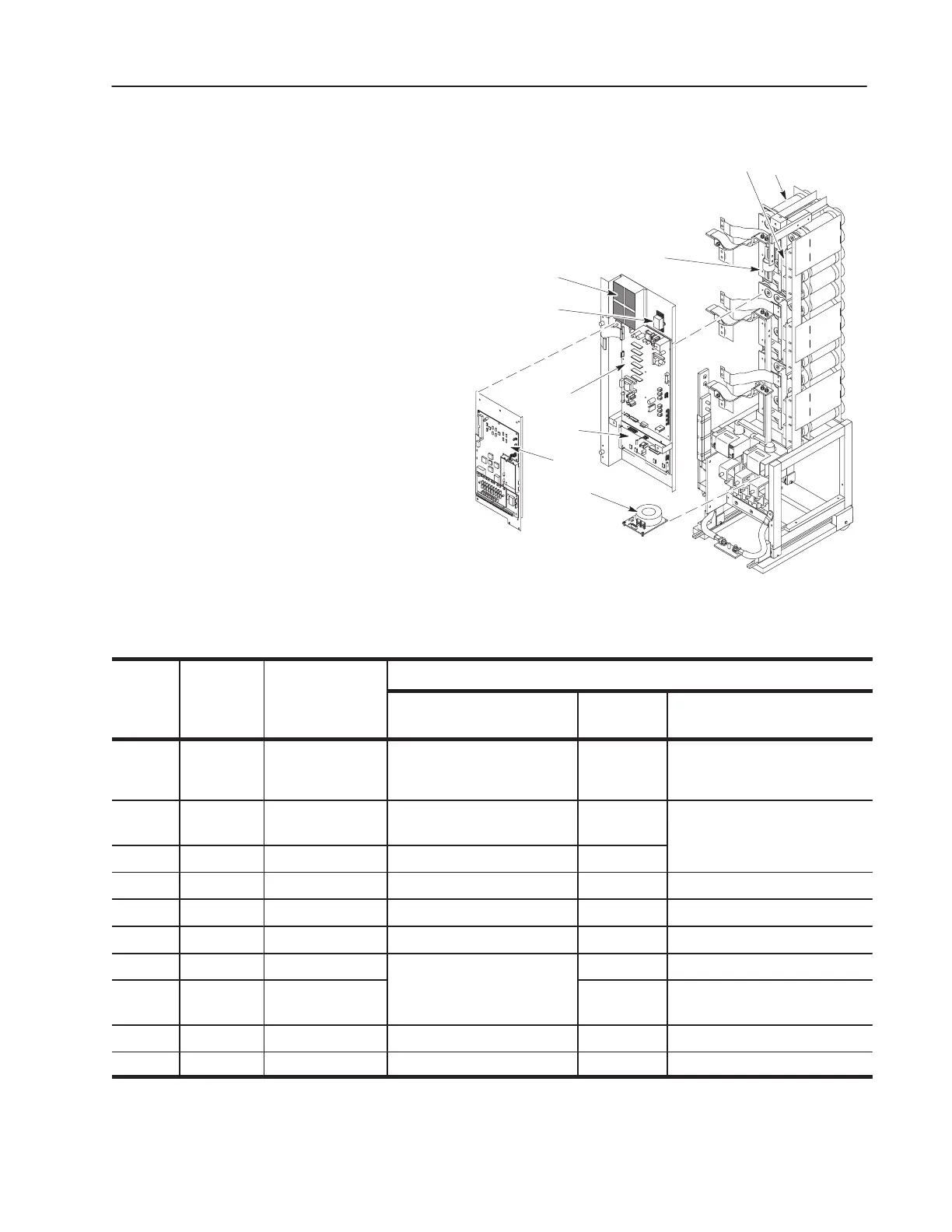
Figure 6.4
Capacitor Assembly Replacement Parts
38
35
40
32, 33
36
37
31
34
39
Table 6.D
Capacitor Bank Assembly Replacement Parts
Symbol on
Procedures
Callout
Chapter 7
Schematics
Description
Access
1
(Ref: Ch. 3)
Test
(Ref: Ch. 4)
Replacement
(Ref: Ch. 5)
31 C1 – C36 Bus Capacitors Removing the Motor Bus
Pulling the Capacitor Bank
Assembly
2
DNA Replacing Bus Capacitors
32 R1 – R9 Volt-Sharing
Resistor
DNA
2
Test 3
Replacing Volt
Sharing Resistors
and Dual Diodes
33 D1 – D2 Dual Diode DNA
2
DNA
34 F1 – F3 Bus Fuse, 350 amp DNA DNA Replacing Bus Fuses
35 – Power Supply DNA DNA Replacing the Power Supply
36 R1 Relay DNA DNA DNA
37 A1 Gate Driver Board
Removing the
ontrol Board
Test 1 Replacing the Gate Driver Board
38 A10 Common Bus
Precharge Board
ounting
late
DNA Replacing the Precharger Board
39 MAIN CTL Control Board DNA DNA Replacing the Control Board
40 CT1, CT2 Current Transducer
Removing the Motor Bus
DNA Replacing Current Transducers
1. Access always requires the procedure: Opening the Drive Enclosure.
2. Access also requires the procedures: Removing the Control Board Mounting Plate and Removing
the Precharge Board Mounting Frame.
 Loading...


